
The next major part of the 10-point mould to reassemble is the crossblock. This block forms one side of the casting cavity as well as the bottom of the type and the jet. After casting it slides sideways, cutting off the jet in the process, allowing the type to be ejected from the mould. A cam in the base of the mould moves an ejector to push out the jet, where it drops back into the metal pot to be remelted.
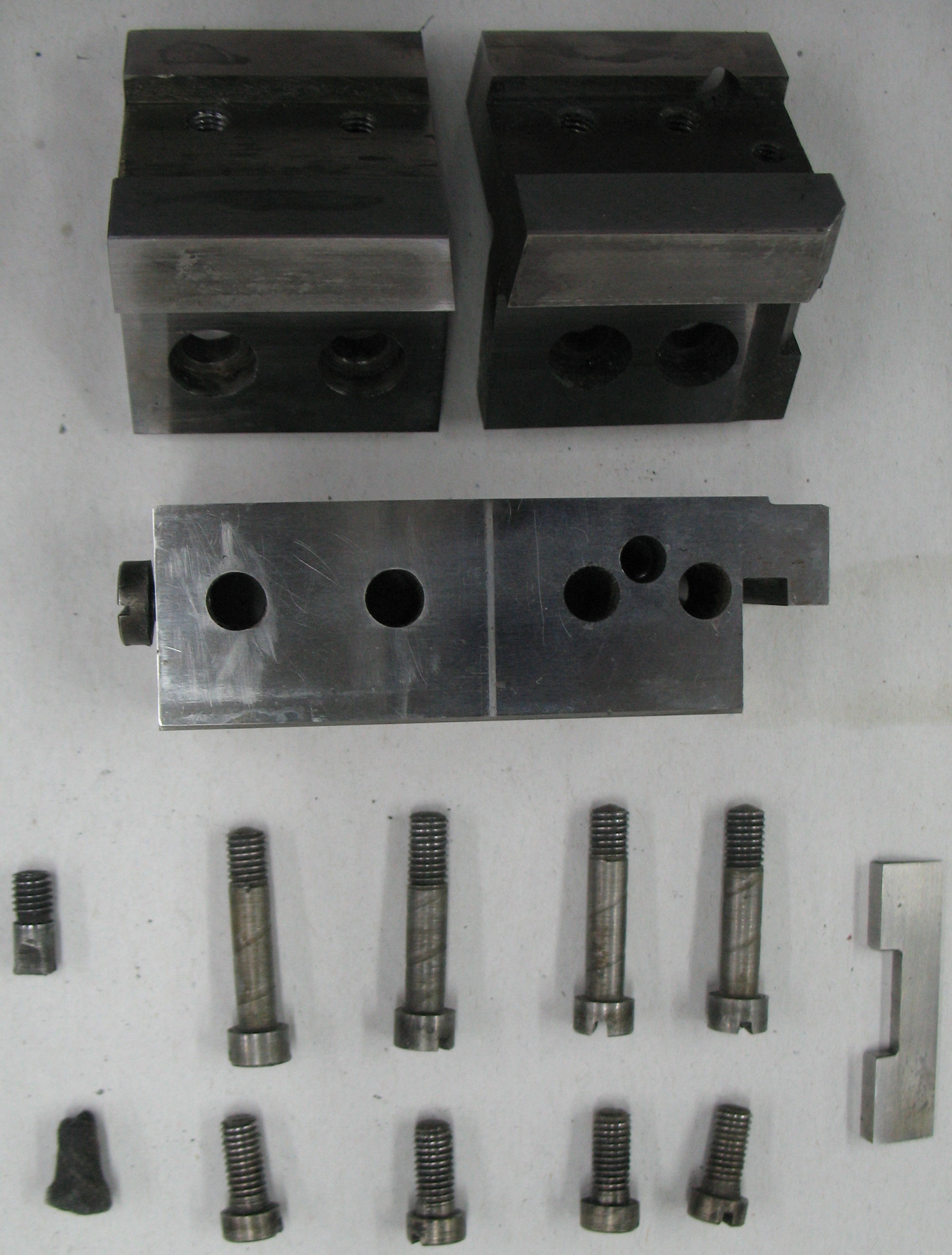 The crossblock consists of four major pieces, a felt pad, and ten fasteners. The main body is in the center of this photo, and the adjusting screw is already installed in the end of it. The surface shown in the photo is the underside of the body, and the surface facing the top of the photo is the one that forms one side of the mould cavity.
The two parts at the top of the photo are the Gate Blocks (“gate” is another term for “jet”, the scrap part of the casting where the molten metal is injected), which attach to the body with a fine adjustment to set the width of the V-groove for the jet ejector. The Left Gate Block (on the right) is positioned by the dowel, essentially a threaded post, which fits into the extra hole visible on one side of the main body. The adjustment screw is then used to position the Right Gate Block so the jet ejector fits properly. Each gate block is held to the body by four screws. The Gate Blocks form the foot of the type and two sides of the jet.
The felt pad fits into the Left Gate Block and serves to spread oil along the lower sliding surfaces of the crossblock. This pad does not have its own oil supply, but just smears around whatever oil reaches this area via gravity.
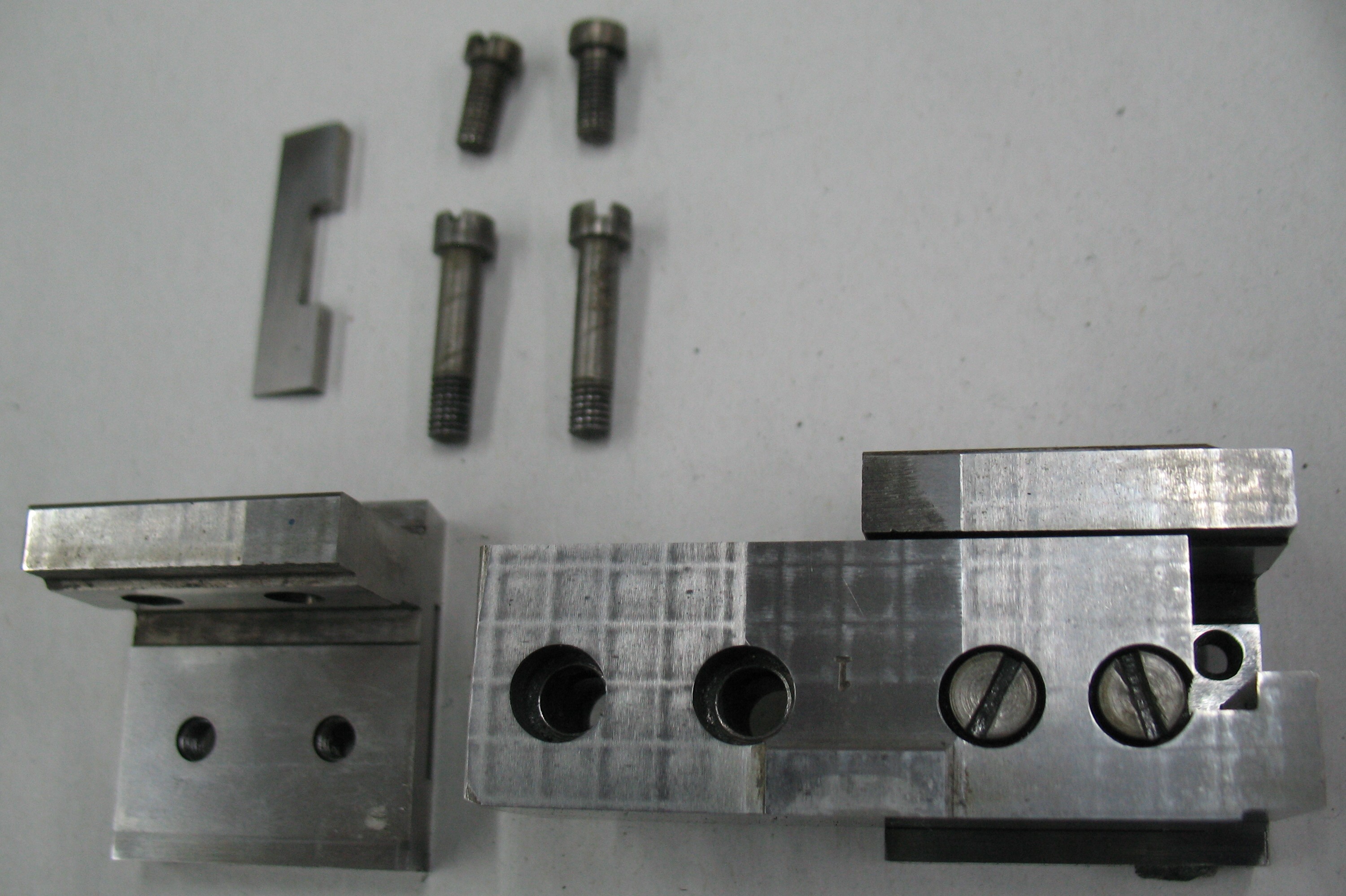 This shows the crossblock right way up with the Left Gate Block installed including the felt pad. The dowel that positions this block is a bit strange: It is threaded about halfway along its length, and has a slot head with the top edges tapered parallel to the slot. Depending on where it stops rotating when it bottoms out in its hole, it may or may not be a snug fit in the matching groove in the gate block because of its tapered sides. On mine, there was perhaps a hundredth of an inch of play in the gate block position, not enough to worry about. Gross mispositioning of this block would mean the jet opening would not be centered over the pump nozzle, and the metal would inject into the mould cavity with excess turbulence, possibly making more porous type.
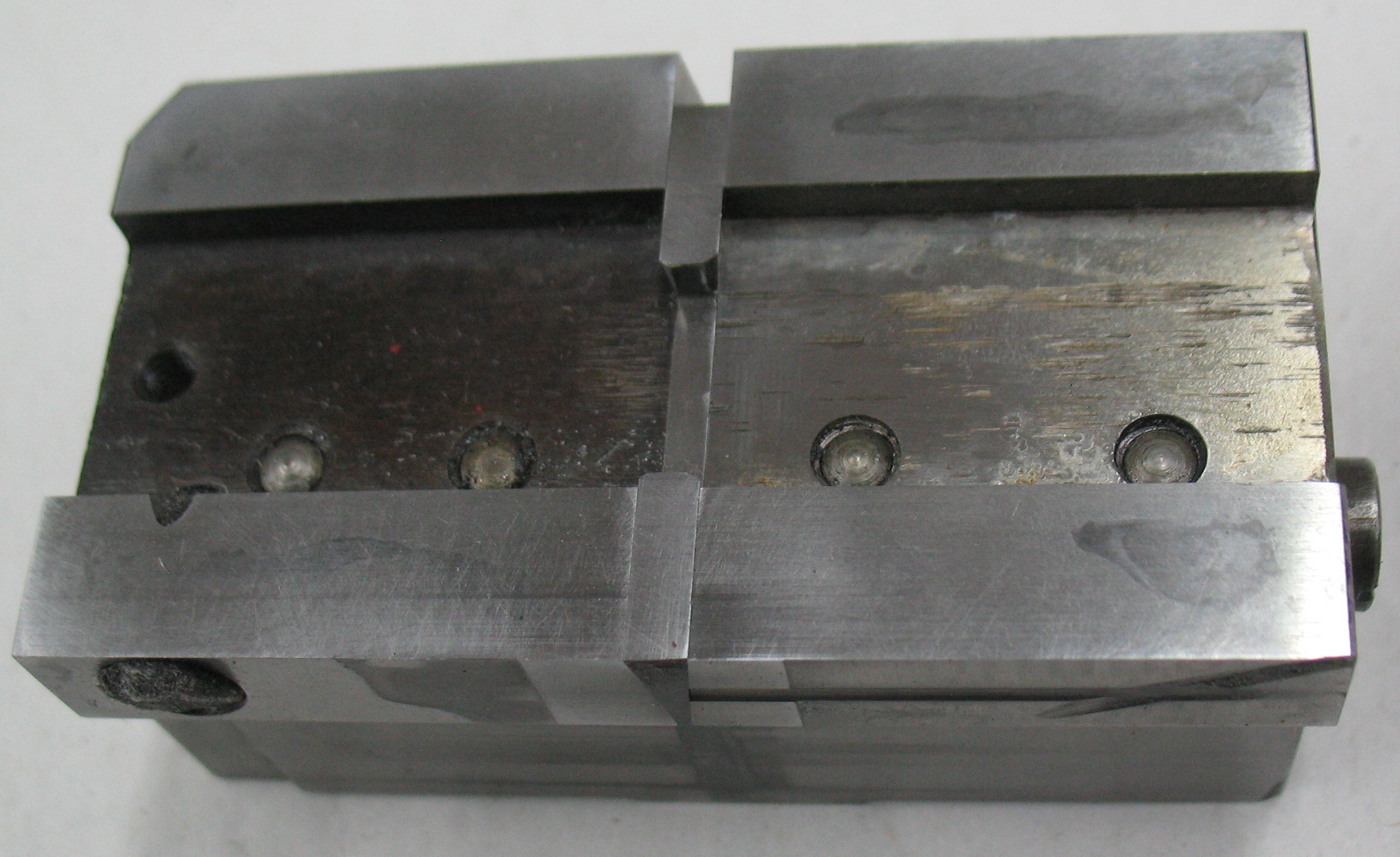 The underside of the assembled crossblock shows the jet ejector in position. The triangular end of the ejector (towards the bottom of the photo) forms the third side of the jet.
The vent groove added by Hartzell can be seen running towards the right from the jet ejector.
The Right Gate Block has been adjusted close enough to the left one so that the ejector has no sideways play but not so close that the ejector can’t seat fully into its slot. This adjustment is easier with no oil, or only a thin film of very light oil, on the ejector, as a heavy film of oil will make it act thicker than it really is.
Both gate blocks must be tightened down carefully to ensure they are properly seated against the crossblock body. All four screws in each gate block must be tightened in sequence a bit at a time, starting from when they first start to snug down.
Leave a Reply