
I’ve started making an 18-point spacer for one of my US Monotype display moulds per the drawing in my last post.
The material I started with was ⅜×¾″ hot-rolled steel because I had a piece handy. The bar was about 8″ long so I started by milling off the two sides to narrow it down to ⅜×½″. This will give me spare stock in case I want to make others. This stock will work for up to 24-point spacers.
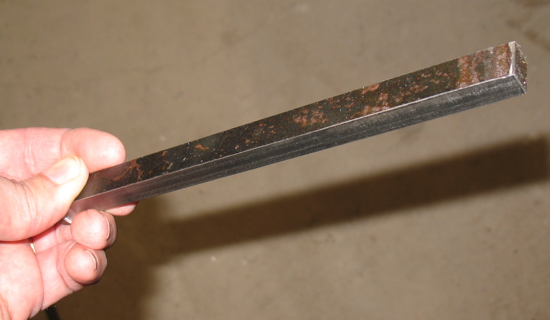
Stock milled to ⅜×½″. Top and bottom surfaces still have black mill scale on them.
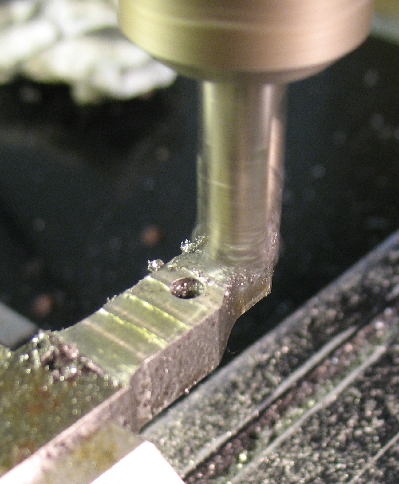
I clamped the stock in my milling vise with one end extending about 1⅜″ and started by drilling the hole right along the center line, a little over ⅝″ from the end. Once this was drilled, I used its location as the origin for CNC milling the outline of the spacer using 3/8″ endmills (first a roughing mill, then a regular one for removing the last 0.005″).

The hole has been drilled and the mill origin will be set to this location.

Using a ⅜″ roughing mill to remove most of the excess metal.
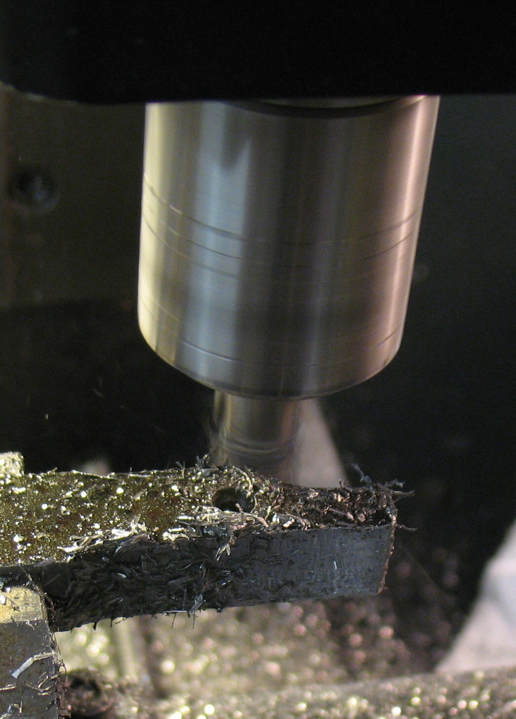
A regular ⅜″ endmill is cutting the final pass of the outside contour. This “final” pass was run a second time offset a bit because the mill turned out to be slightly under its nominal diameter, leaving the part too wide.
This gave most of the ‘d’-shaped outline of the spacer. The remaining end will be shaped once the spacer is cut from the stock, but for now the stock makes a good handle for securing the work.
The next step was to surface-mill the top and bottom of the part to reduce the metal from ⅜″ down to somewhat more than the 0.2501″ target thickness. Any remaining metal removal would be done by hand using a file or diamond grinding stones. Rolled steel commonly has locked-in stress in its surface layers, so this thinning was done 0.010″ at a time, flipping the part over for each pass so the removal was symmetric to avoid warping.
Surface milling the part to get it near the correct thickness.
I was not sure how much metal I would have to leave for surface finishing. My mill is a bit out of tram (the spindle is a tiny amount off vertical) so the successive passes of the endmill leave a very slight sawtooth shape (which I found on measuring to be less than 0.001″ deep). Despite placing an adjustable parallel under the bar before clamping it in the vise each time, it is also apparently a little off level because the metal is about 0.003″ thicker near the stock compared to near the tip.

Uneven milled surface. The wide smooth area farthest from the end was caused when the endmill took a slightly heavier bite and the vibration and downward pull (from the spiral shape of the cutter) draw the milling head down to the lower limit of its backlash. The other stripes are due to the mill being out of tram.
I also ran into problems with the Z-axis backlash on my mill, which is around 0.008″. The weight of the mill head is imbalanced so it does not drop under its own weight to take up the backlash; when moving down, the leadscrew is actually pushing the head down. Once you start cutting, though, forces on the tool can be enough to pull the head down, at which point it suddenly starts cutting 0.008″ deeper. This happened on the last cut just before the photo above was taken. I had to modify the GCode file to lower the head too far (beside the part) and raise it up again to the desired depth in order to get consistent cutting depth.
I am using a new (to me) software tool (CamBam) to convert my part drawing to GCode and I’m still not entirely familiar with this program. I did not see any feature for surface milling a raised surface, so I told it to mill a pocket instead as this would also produce the movements required for surface milling. Before doing this I had to enlarge the apparent size of the part so the milling passes would start and end completely beyond the edges.
Removing 0.010″ using a hand file looks like it should be easy enough to do, so I plan to stop the machine work at a thickness of around 0.260″.
Once I had reached about the right thickness, I used a hacksaw to separate the part from the stock. I finished the cut end with a few passes sidecutting with the endmill, and used a file to round the corners. As a result, the outline of this part differs from the drawing insofar as these two corners are not necessarily 1/16″ radius. Also, because the cutting was done with a ⅜″ endmill, the radius of the inside corner by the sloped side is larger than 1/16″.
I filed the milling marks off both faces and ground them a bit to get some idea of the metal removal rates of my three diamond grinding “stones”, and the thickness now reads 0.2627″ so I have about 0.0125″ to remove.
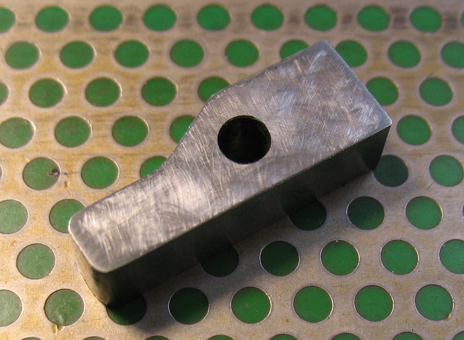
The spacer separated from the stock and with its faces polished up a bit to remove the milling marks
I’ll cover getting it to its target thickness in another post.
Leave a Reply