
My first attempt at making a rubber mould of a Lanston display matrix ended up with a fatal flaw due to an air bubble.
I made a second attempt, hoping to avoid repeating this flaw.
The instructions for the casting resin recommend applying a vacuum to the mould after filling it with resin in order to expand any bubbles, causing them to either pop or float up through their own enhanced buoyancy. I do not have a vacuum pump readily available so I will have to try pouring the resin very carefully and using a fine probe to poke around in all the nooks and crannies of the mat.
Having used the resin once, I decided that it was not necessary to seal the sides of the casting cavity since any resin leakage would be minimal. Sealing would probably still be needed if I were to use a vacuum to remove bubbles.
I also had a better estimate of the amount of resin required to fill the cavity, so I mixed less this time than last.
I poured the resin into the cavity of the matrix very carefully, allowing it to flow on its own along the contours of the type so as to minimize the chances of trapping an air bubble. I also used the tip of a fine copper wire to probe the perimeter of the cavity of the matrix.
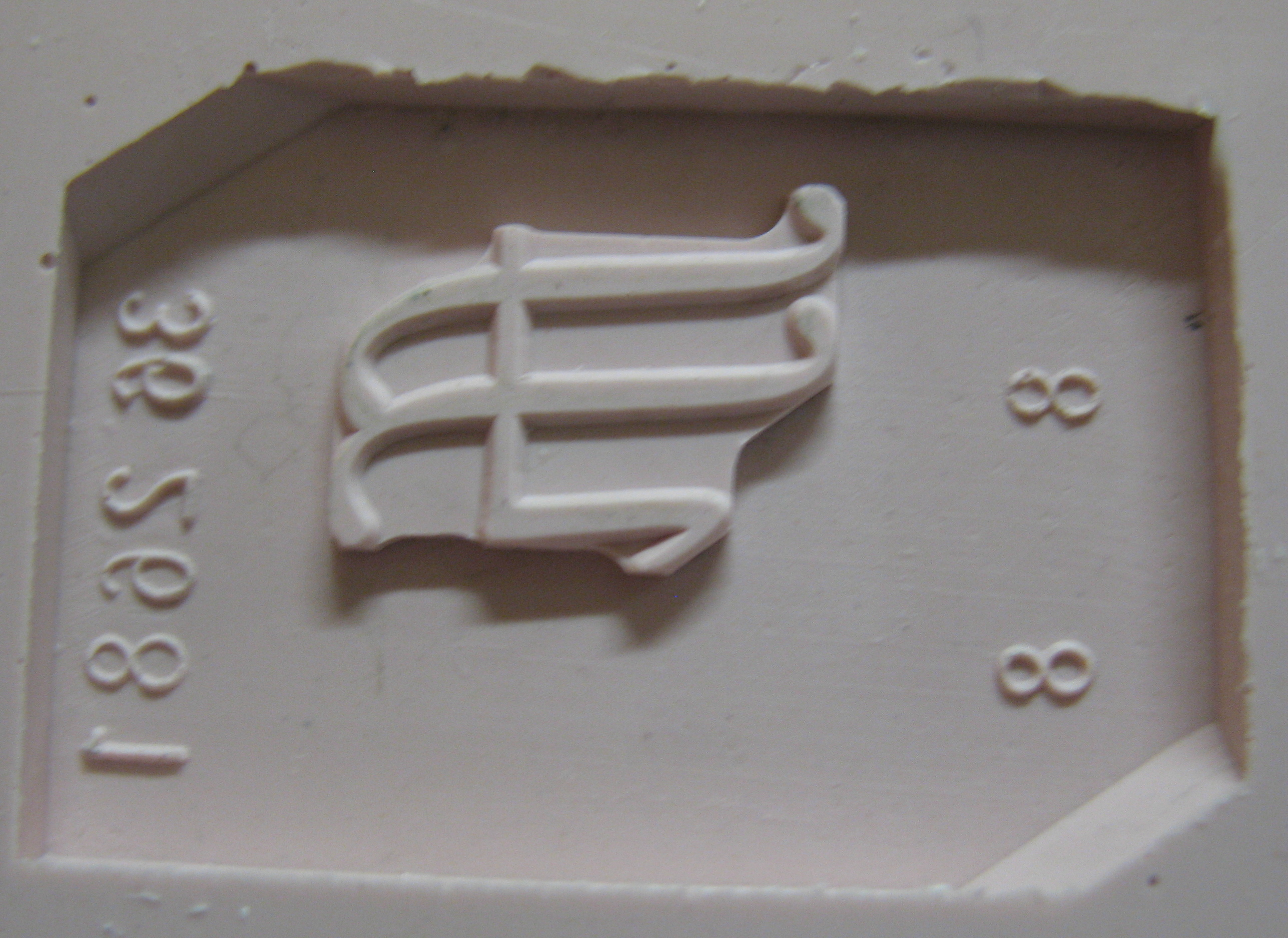 The resulting cast was a success, with no bubbles around the letterform. As well, most of the dirt had been stripped off the mat in the first casting, so this one was much cleaner.
The colour balance of this photo is incorrect. This casting has the same pink colour as the previous one.
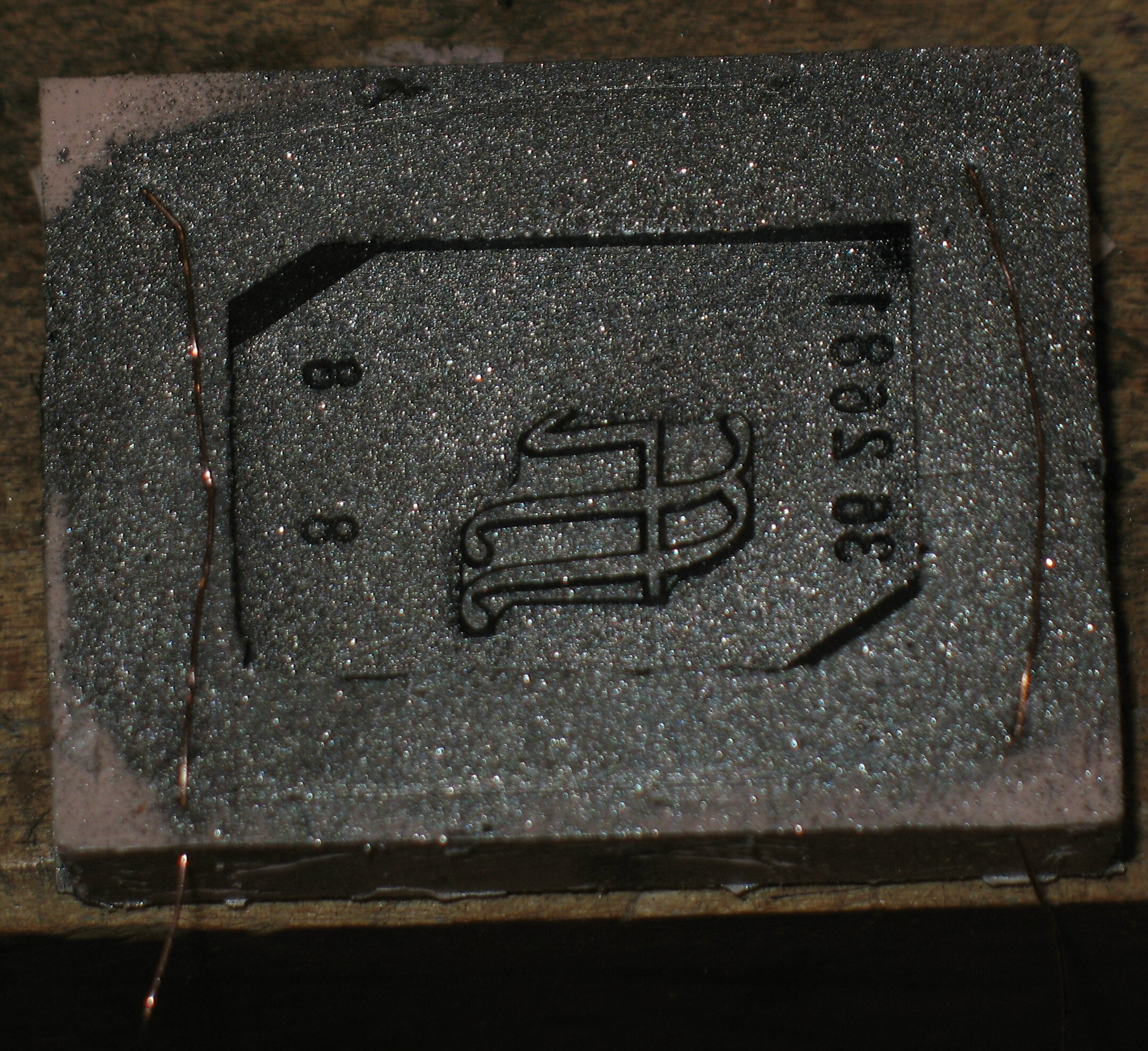 For the electrical connection for electroforming, I stripped the insulating varnish off some #32 magnet wire, threaded it through the edge of the rubber mould and along its surface, and poked the free end back into the rubber. This held the bare wire more or less in continuous contact with the surface of the mould.
Then I put some of the graphite powder we sell as a papermaking pigment into the cavity of the mould and overlapping onto the wires. I shook off the excess and used a small paint brush to brush off more of the graphite. The graphite is conductive enough to cause the copper to plate over the entire surface, and also acts as a release agent (although I’m not sure if that is necessary with this rubber).
The plating bath and copper anode I used also came from Lacy & Co. but the directions are pretty vague: use between 3 and 9 volts. I settled for adjusting the voltage to produce 200mA of current (this took about 2 or 3 volts).
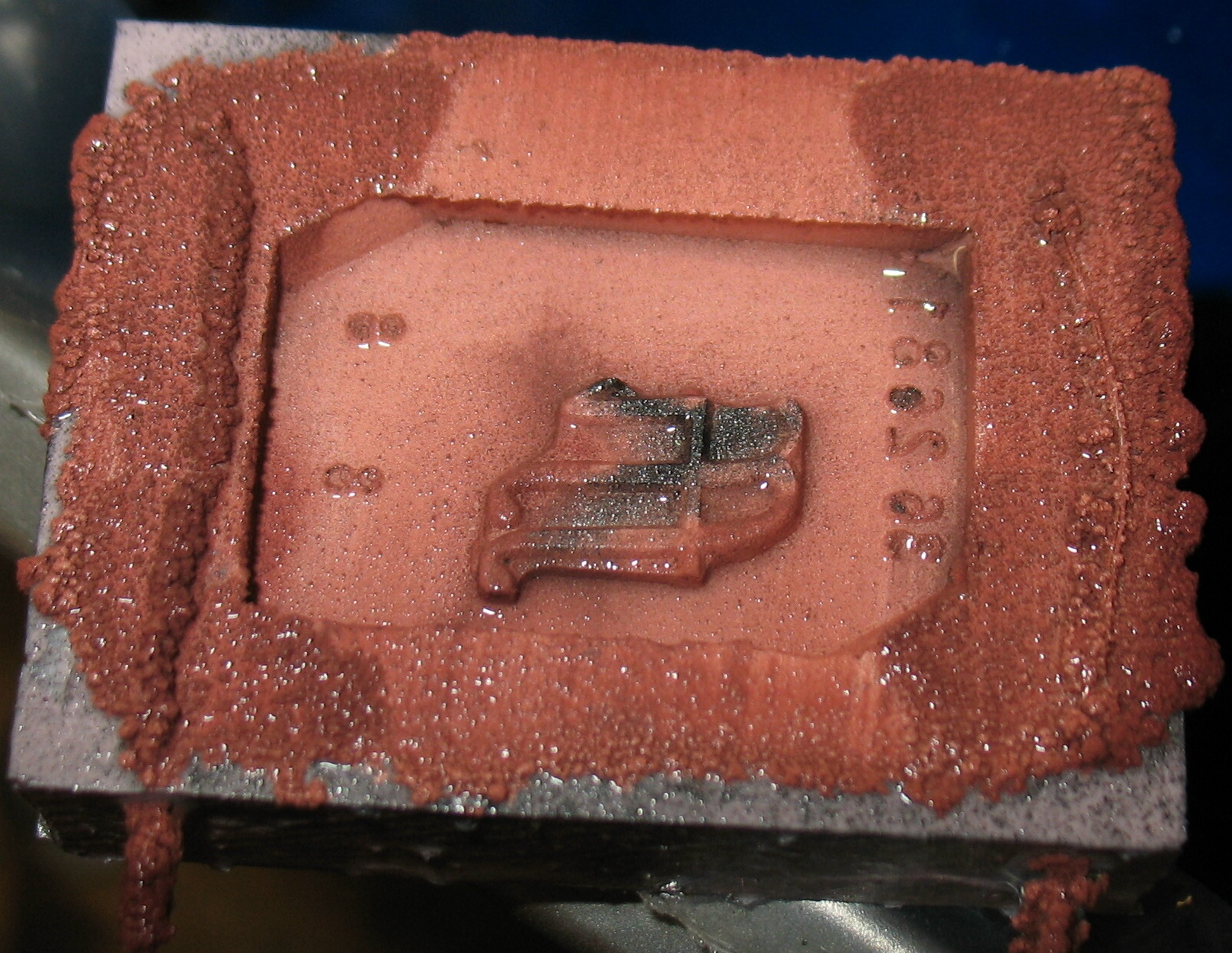 After a few hours of plating, the copper had spread almost completely across the face of the matrix. A bit of the graphite is still visible in the middle. Another hour or two and that was copper-covered as well. The freshly-plated copper has a rather striking reddish colour, quite distinct from the copper colour one normally sees.
Once the surface was covered, the task remained to continue plating until the matrix was thick enough. Because of the plating characteristics of the copper, this is turning out to be harder than expected.
More on this in another post…
Leave a Reply