
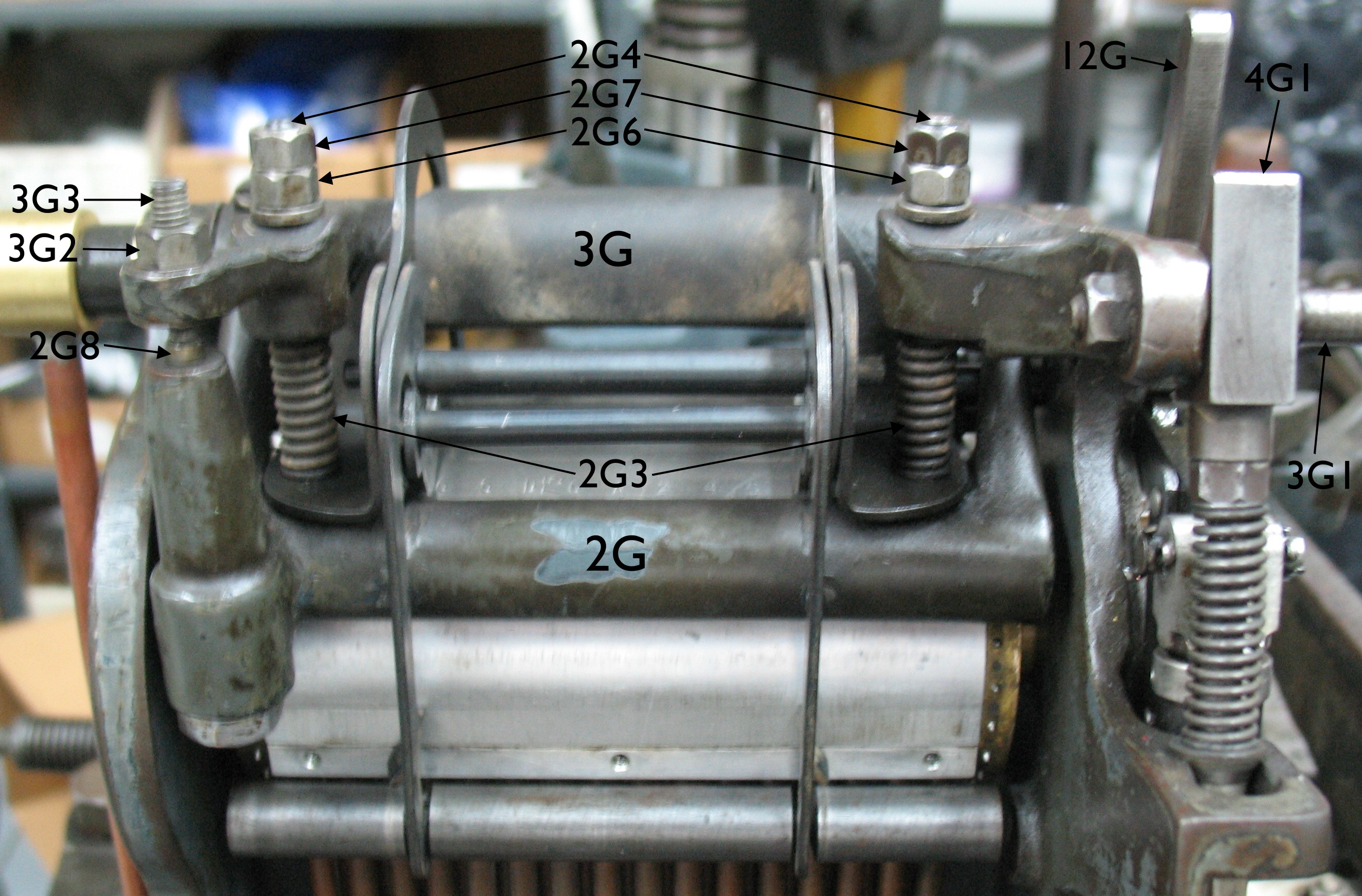
 Once the operating rod for the paper tower is adjusted, there are four adjustments left, all affecting the Air Bar 2G, Pressure Bar 3G, and air feed. Two of the adjustments are on the Connecting Bar 4G that links the Paper Tower Lever to the Clamping Lever, one is the screw 3G3 that actuates the air valve stem 2G8, and one is the stop nuts 2G6 that limit how far the Air Bar Springs 2G3 can expand. The two adjustments on the Connecting Bar are the overall length of the bar and a stop that limits is upwards travel. On older casters before serial number 503 the latter adjustment did not exist; instead there was a simple spacer tube and wear was compensated for by adding a washer to the end of the spacer tube.
The adjustments in Casting Machine Adjustments consists of setting the valve screw 3G3 to a specific amount of projection below the arm it is set in. Then a sheet of caster ribbon is used as a feeler gauge between the 3G3 screw and the valve stem, allowing the Air Bar Spring length to be adjusted. Third, the connecting bar length is adjusted to set the clearance between the air bar and the cross girt to three ribbon thicknesses just as the clockwise rotation of the pawl ring stops (and thus the ribbon stops). Fourth, the stop collar on the connecting bar is adjusted so the connecting bar has about 2 points of total motion. The book mentions that these adjustments interact with each other and that it might be necessary to repeat some of the earlier adjustments.
I have an alternative adjustment procedure which generally avoids the need for repeating adjustments, and also does not rely as much on rote distances.
First, a look at the parts of the connecting bar. It is a bit difficult to see how the adjustments work on the assembled rod, and the books don’t elucidate much.
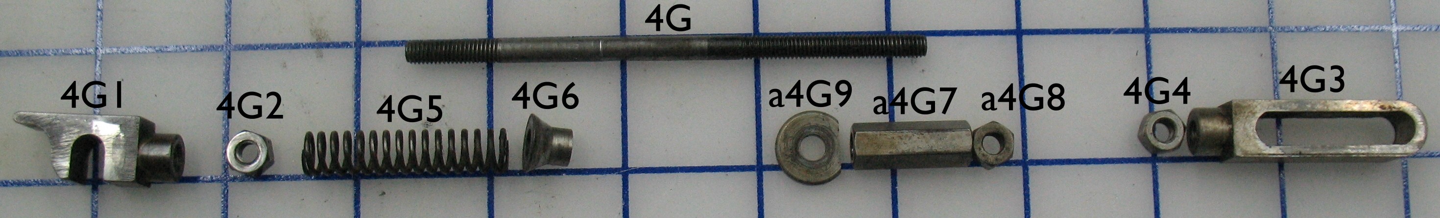
The top end of the rod 4G (on the left of the above photo) has a left-hand thread, as do the top link 4G1 and its locknut 4G2. The sleeve a4G7 is threaded near its lower (right in photo) end but the rest of it is a clearance hole that can slide freely over the 4G rod. The two adjustments of this bar consist of:
- Length adjustment: The locknuts 4G2 and 4G4 are loosened and the rod is rotated (using the sleeve a4G7 still locked by its locknut a4G8). Clockwise rotation of the rod (when viewed from above) shortens the bar, and overall there is about half an inch of adjustment range available. When assembling this bar one should try to ensure that both ends 4G1 and 4G3 are threaded onto the rod by the same number of turns so the length adjustment is not limited by one end either unscrewing completely or bottoming out prematurely.
- Upward motion limit: The locknut a4G8 is loosened and the sleeve a4G7 is turned to adjust how far the bar can rise before the washer a4G9 strikes the underside of the lug on the air tower housing. The rod itself should not rotate as the length adjustment locknuts should be tight.
The adjustment sequence I use is:
- Adjust the bar length so the air bar presses hard enough on the ribbon to limit air leakage to an acceptable value.
- Adjust the bar sleeve so the air bar does not move from its raised position until the ribbon has stopped moving.
- Adjust the stops on the air bar pressure springs so the air bar does not lift too high off the cross girt.
- Adjust the air valve operating screw so the air valve opens at the correct time, just after the air bar seats.
Bar Length Adjustment
Start with the rod adjusted to its longest practical length, with each end screwed on about 3 turns, the sleeve locknut a4G8 tight against the sleeve a4G7 , and the two length adjustments locknuts 4G2 and 4G4 backed about ¼″ from their respective end pieces. The stop nuts 2G6 and 2G7 on the air bar should be at the top of their studs 2G4. Turn the caster handwheel until the air tower lever is at its full down position and the pin jaws have started to close. Load an unpunched ribbon into the reader, lower the ribbon feed lever 12G to stop ribbon advance, clip the rod end 4G1 onto the pin 3G1 on the pressure lever, and apply air to the caster. If necessary, loosen the locknut 3G4 on the air valve adjusting screw 3G3 and turn the latter clockwise until air starts to flow to the air bar.
The air bar is likely not contacting the ribbon and air is escaping freely. Shorten the rod by turning the sleeve a4G7 (and thus the rod 4G) clockwise; at first the air bar will contact the ribbon but continue to leak air, but as the rod is shortened, the springs 2G3 will start to compress and more pressure will be applied to the air bar, gradually reducing the air leakage. As the ribbon is slightly porous the leakage can never be eliminated, but once the rod is shortened appropriately one can tell from the sound of the leaking air that the air bar has made the best seal that can be achieved.
Turn the caster by hand through a few cycles to ensure that the good seal persists from one cycle to the next. Once you are satisfied that the air bar is sealing well, tighten the locknuts 4G2 and 4G4. Disconnect the air supply but leave the ribbon in place.
Bar Sleeve Adjustment
With the caster in the same position (pin jaws closing), loosen the sleeve locknut a4G8 and adjust the rod to give a space of about 2 points (about 0.036″) between the top of the sleeve and the underside of the lug that the rod 4G passes through. Tighten the locknut again. I recommend using two wrenches (one on the sleeve, one on the locknut) to avoid accidentally loosening the rod end locknuts and losing the rod length adjustment.
This is the same as the adjustment specified in the book, but here is the rationale for the choice of distance, which will provide some guidance for altering this value: On a caster in new condition, this distance is sufficient to move the air bar from having enough clearance for free ribbon movement to clamping onto the cross girt. I suspect that 2 points was selected because the writers thought it was more likely that a casting shop would have some 2-point leads lying around that a set of mechanic’s feeler gauges.
As parts of the air bar and clamping lever wear, however, this distance must increase a bit, since the linkage alternates from lifting to pulling down and so any play that has developed must be taken up by extra rod motion.
There are however two reasons not to make this clearance too large: One is that there will be excess motion of the clamping lever on each cycle of the machine, causing more wear. More importantly, however, is that it is essential that the bar remain motionless during the downward stroke of the air tower lever until the pawl ring lug hits its stop and the ribbon motion stops. Otherwise the air bar will start to clamp before the ribbon has stopped advancing and the ribbon tractor holes will be damaged.
This latter condition must be verified absent by visually inspecting the motion of the pawl ring and the rod. Raise the ribbon feed lever so the pawl ring goes through its normal rotation. The book recommends using a slip of paper to determine when the pawl ring lug has hit its stop; at this point the pin in the lower link 4G3 of the bar must not yet have contacted the bottom of the slot in the link and the sleeve must still be tight to the underside of the lug. If this cannot be achieved, the connecting bar will have to be lengthened a bit, in turn perhaps requiring that the air tower operating rod be shortened so there is still a good air seal despite the longer connecting bar.
Air Bar Pressure Spring Length Adjustment
Turn the caster handwheel until the air tower lever is at its uppermost position. Loosen the two 2G7 locknuts on the studs on the air bar. Ensure that the threads on the locknuts and adjusting nuts are clean so they turn easily on the studs using only your finger.
At this point in the adjusting sequence the air bar is likely still pressing against the girt so the adjusting nuts 2G6 should be tightened to raise the air bar. To compensate for wear, manually pull down on pin 3G1 so it presses against the bottom of its matching notch in 4G1 while turning the nuts—this requires a bit of finesse in order to take up the play in this joint but not compress the rod spring 4G5. The nuts will turn freely by hand until they contact the pressure bar, at which point any further tightening would lift the air bar off the girt. From this point of contact with the pressure bar, each of the 2G6 nuts should be turned an additional ⅛ turn clockwise. This is equivalent to providing 2 to 3 ribbon-thicknesses (0.006-0.009″) of clearance under the air bar as recommended in the books. Turn each locknut 2G7 by hand until it contacts its adjusting nut. Use a wrench to hold the locknut motionless and use a second wrench to back the adjusting nut tight against the locknut. Just to repeat that last bit: hold the locknut and turn the adjusting nut. If you do the normal procedure of holding the adjusting nut and tightening the locknut, the adjusting nut will be pushed down by the amount of clearance in the threads, which is probably another ⅛ turn or more, throwing the adjustment off by that amount.
To check the adjustment, manually release the locking pawl (press on the lever that engages the Repeating counting wheel) and turn the ribbon feed to ensure the ribbon moves freely. Then position the caster handwheel to the point where the pin jaws are closing, and ensure that the air bar springs are compressed. There will be only a tiny amount of compression but it is sufficient if the washers under the 2G6 adjusting screws are both loose enough to turn. If this does not occur repeat the Bar Sleeve Adjustment, which may have been inaccurate due to wear in the clamping lever being masked by the upwards pressure of the air bar springs.
Air Valve Adjustment
Again with the air tower lever in its uppermost position, loosen the locknut 3G2 and turn the adjusting screw 3G3 so that a piece of ribbon placed between the screw and the valve stem is gripped but can be pulled out, then tighten the locknut and double-check the clearance. This setting (about 0.003″ clearance) ensures that the air valve will open just after the air bar seats on the ribbon and the air bar springs start to compress.
Cycle the machine with a perforated ribbon in place and air supply on to ensure the air valve opens. If it does not, the Bar Sleeve a4G7 will have to be adjusted a bit for more motion of the pressure lever.
Leave a Reply