
My last post about this project was over a year ago, wherein I mentioned that I had purchased the aluminum stock to make the main parts of the valve unit. A lot has happened since then, to the point where I brought it along with me to the 2016 ATF conference to see how it fitted on other casters.
Here is how the valve body looked when I first tried it on my caster (July 2016):
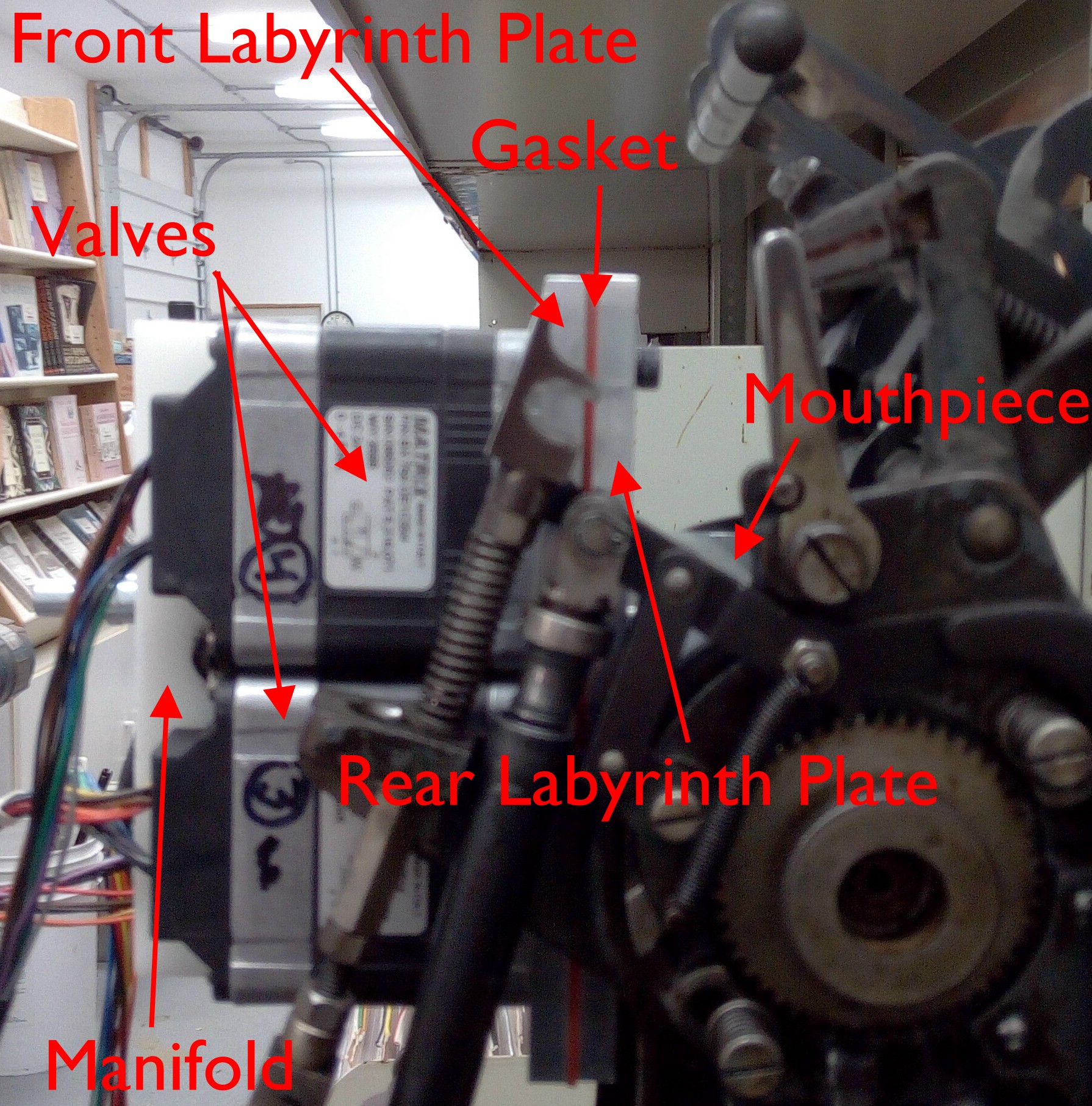
The valve body installed on my caster as proof of concept.
Briefly, the compressed air comes in through the manifold and is distributed to the four pneumatic valves. The manifold also connects all the dump ports where the air is released when a valve is closed. Each valve controls eight air channels, which emerge on the far face of the valve arranged equally around a circle. The two labyrinth plates and the gasket between them carry the air from these four circular port arrangements to a single row of 31 ports on ⅛″ centers (one valve port is blind), to match the layout on the caster’s paper tower. An aluminum mouthpiece angles the ports by 45° so they meet up with the ports on the paper tower cross girt.
This is similar to the unit made by Krzysztof Słychań, but it uses machined channels rather than hoses and fittings to connect the valves to the caster ports.
The valve body has arms which hook onto one of the crossbars of the paper tower, and the weight of the valve unit provides enough pressure to seal a gasket between its mouthpiece and the paper tower cross girt.
Eventually all the electronics will be on a circuit board around the manifold, and an arm will link to the connecting hook to detect the part of the caster cycle where the air valves should be open. The unit will be fully self-contained, with just a power cord, compressed air inlet, and USB port. As with Bill Welliver’s interface, it will still use a computer to run it.
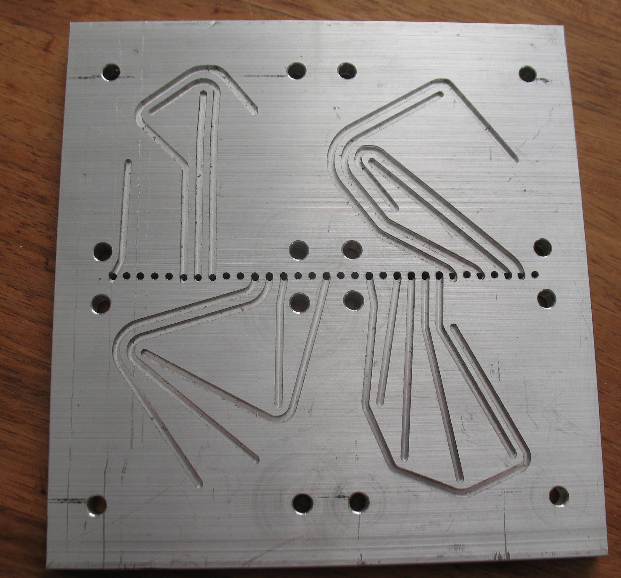
The rear labyrinth plate. Some passages penetrate to this layer directly from the valve ports and follow the channels to the outlet ports along the center line. The remaining passages follow channels in the front labyrinth plate directly to the output positions. This was the first plate I made, and you can see some misalignment between the holes and channels due to a loose clamp bolt on the mill.
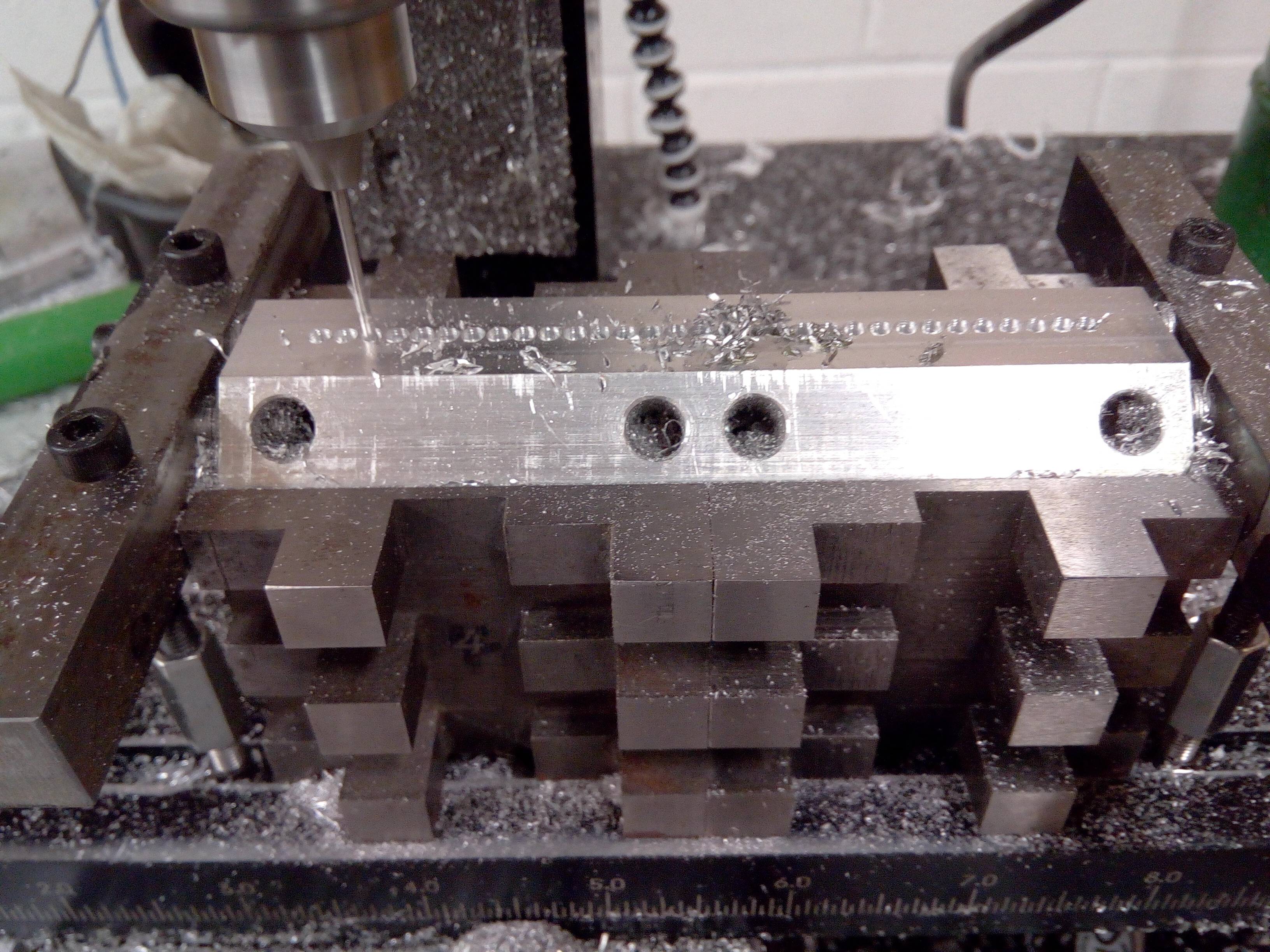
Drilling the air passages in the mouthpiece. This this involved some tricky work holding because of the 45° bevel involved.
The valve body is a close fit on the paper tower. I don’t want it too sloppy because this might allow too much misalignment between the output ports and the ports on the paper tower. On the other hand, too close a fit makes it too tight to put in. The only dimension I had to work from was the width between the side covers of the paper tower on my caster, and I have no idea what manufacturing tolerances are involved. To see how well it fit on other casters, I brought it along with me to the ATF conference in upstate New York
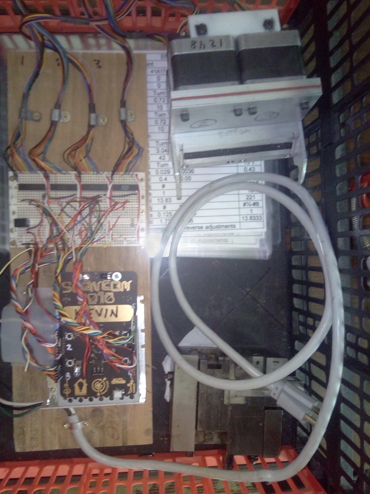
My Show and Tell goodies for the ATF conference
The electronics for the controller included a power supply, a microcontroller in the form of a Maker conference badge, and the drivers for the valves wired up on a breadboard. Everything was mounted on an ugly piece of plywood. The bin also contained an unusual Monotype mould for making cored type (I think it was 24-point), and a few laminated caster adjustment cheat sheets to pass around.
The microcontroller was not yet ready to do actual casting work, but I had it programmed to run the air channels sequentially, holding each one for about a second before switching to the next.
I got to try the valve body for fit on three of Mike Bixler’s comp casters, but unfortunately it would only fit on one, and even there is was a tight fit. This was during the show-and-tell segment of the conference, and there were a few interested people having a look and asking questions. Unfortunately I seemed to be spending most of my time explaining that the software was incomplete and only running a test cycle, as that was ultimately the answer to several of the questions.
I also hooked up compressed air to the valve to see how well the caster reacted. Some of the air pins snapped up smartly when activated, but others were sluggish or just didn’t move at all. I had seen similar results on my own caster, but I didn’t have a record of which ports worked well and which did not.
So my take-home from this was that:
- There is some interest in this from ATF members
- I need to make the body a tad narrower to ensure it fits all casters
- I need to look into poor air flow problems
Hi there,
nice to see your progress – my controller is pretty much done and the only thing that remains to be done is typesetting software.
I wouldn’t use a fixed plate for connecting the valves to the paper tower. We tried something like that with John (see the “square box” at http://www.metaltype.co.uk/forum/index.php/topic,1099.0.html ) but it tended to slide down a bit under its weight, obstructing the air holes and cutting the flow off. We decided that the valves+electronics should be attached separately, and I devised a clever way of doing so, using the original Monotype takeup spool. You can see the new design on the second page, I made it a year ago, deployed at the Book Art Museum in Lodz, Poland and it’s working fine :).
I think I may be saved from the “slide down” problem because I’m not hooking the interface on the tractor wheel shaft. Instead I’m using the Connecting Link Fulcrum Pin (18G8) shown on plate 22 in Monotype Corp.’s Spare Parts List and on page 66 of the Lanston Plate Book. Because of the location of this rod, the weight of the interface presses the mouthpiece against the cross girt rather than trying to rotate it around the cross girt.