Someone commented on the conversion I did on my Sherline 2000 mill to allow it to use either the 8-way column base it came with or the rigid rectangular base that comes with the 5000-series mills, so I though I would elaborate on that a bit.
The 2000-series mills have a column base that allows the user to move the column fore and aft, rotate it to either side, tilt it backwards and forwards, and also tilt it side-to-side while setting the mill up for a cut. The base of this column is a round post a couple of inches in diameter, and the base of the mill has a U-shaped recess for the column base post to nestle in.
The 5000-series mills have a column base that is a single rigid block, so the column itself only has one position and orientation, namely square to the X- and Y-axes of motion. The mill base has a straight ledge that the column base fits against.
Neither the U-shaped recess on the 2000 nor the ledge on the 5000 actually provide any precision location for their respective column bases. Rather, they provide a rough position to allow you to get the screws started to hold the column base to the mill base without too much fuss.
I have found that the 8-way column has a tendency to creep during a cut. Even with the mating surfaces cleaned of any oil and the clamps as tight as I can get them, I have found the column drifting out of position during some cuts. Furthermore, the drift in general causes the cutter to take a bigger bite which in turn accelerates the drift. For softer materials like aluminum this is generally not a problem but it is quite a nuisance when cutting steel. Because of this I decided to purchase a 5000-style column base and adapt my mill to accept it. For more versatility in mounting the column I have also added many threaded holes to the base which allow multiple column positions.
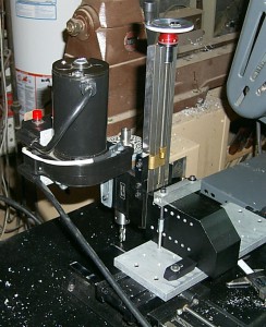
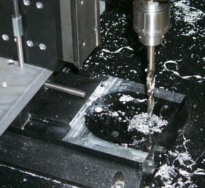
 The column base is the black part clamped to the mill table. The only factory original holes are the two along the vertical centerline of the surface being drilled, and four near the right end of the surface facing down. The former are for attaching the column base to the mill base, and the latter are for attaching the column to the column base. All the other holes in the column base are ones I drilled with the appropriate spacing to allow the column to be attached, as are the holes being drilled in this photo. There are also 14 more matching holes on the back side, and the surface facing down has three holes with the appropriate spacing for the screws that attach the column base to the mill base.
As a result, the column base can be mounted in 4 positions with what would normally be its front face on the bottom, and the column can be attached to the base in 11 different positions. This allows you to work with the milling head at various off-center positions.
Ultimately all these holes will be tapped for the appropriate screws (¼NC20 for the attachment to the mill base, and #10NF32 for attaching the column), but so far I have only tapped the holes as I need to use them.
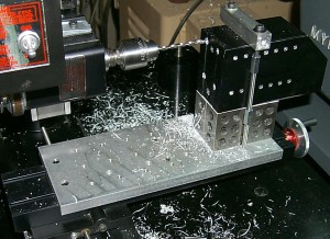
 Once the column base was modified, I turned the mill on itself: I mounted the column on what would normally be the bottom of the column base, and clamped the column base to the milling table with the head facing backwards.
As you can see from the lack of stepper motors this was all done before the mill was converted to CNC.
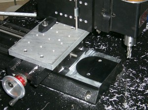
At this point I have the Z height adjusted so the milling cutter just scuffs the black anodizing on the surround of the U-shaped recess.
 A few passes of the mill have cut away the surround. You can clearly see the outline of the U-shaped recess as the black area, and the shiny cut surface marks the surround that used to be there.
Once again, cutting depth was adjusted until the milling cutter just started scuffing the black anodizing in what was the bottom of the recess.
 Strangely, the screws holding the column base to the mill base have a different pattern for the 2000 and 5000 series column bases. The former has the two holes side-by-side while the latter has them fore-and-aft but with the same spacing. I used the same setup to drill two new holes to allow mounting the rectangular column base in its normal orientation. These holes are not countersunk underneath like the original holes but this is fine because the table my mill is mounted on has an opening that allows the screw heads to protrude.
Now I have the choice of the flexibility of the 8-way column base, or I can use the rigid column base and take heavy cuts without wondering if the setup is creeping out of adjustment. All the extra holes in the rigid base allow additional setups, many of which eliminate the need for the “Horizontal milling conversion” that Sherline sells.


Leave a Reply