
In addition to poor flow when open, the other shortcoming of my stock of surplus Matrix pneumatic valves is poor sealing (leakage) when operated in NC mode, where the shutter spring is the only force holding back the flow of air.
The port the shutter seals against is about 0.050″ diameter (based on trying various size drill shanks in the port), so its area is .00196 in² and the force against the shutter when the supply is 20PSI would be about 17.9g. Yes, I realize this is cheating, grams are a unit of mass, not force, but I am referring to weight-equivalent force. In CGS units this would be about 17,500 dynes or in MKS units 0.175N (Newtons).
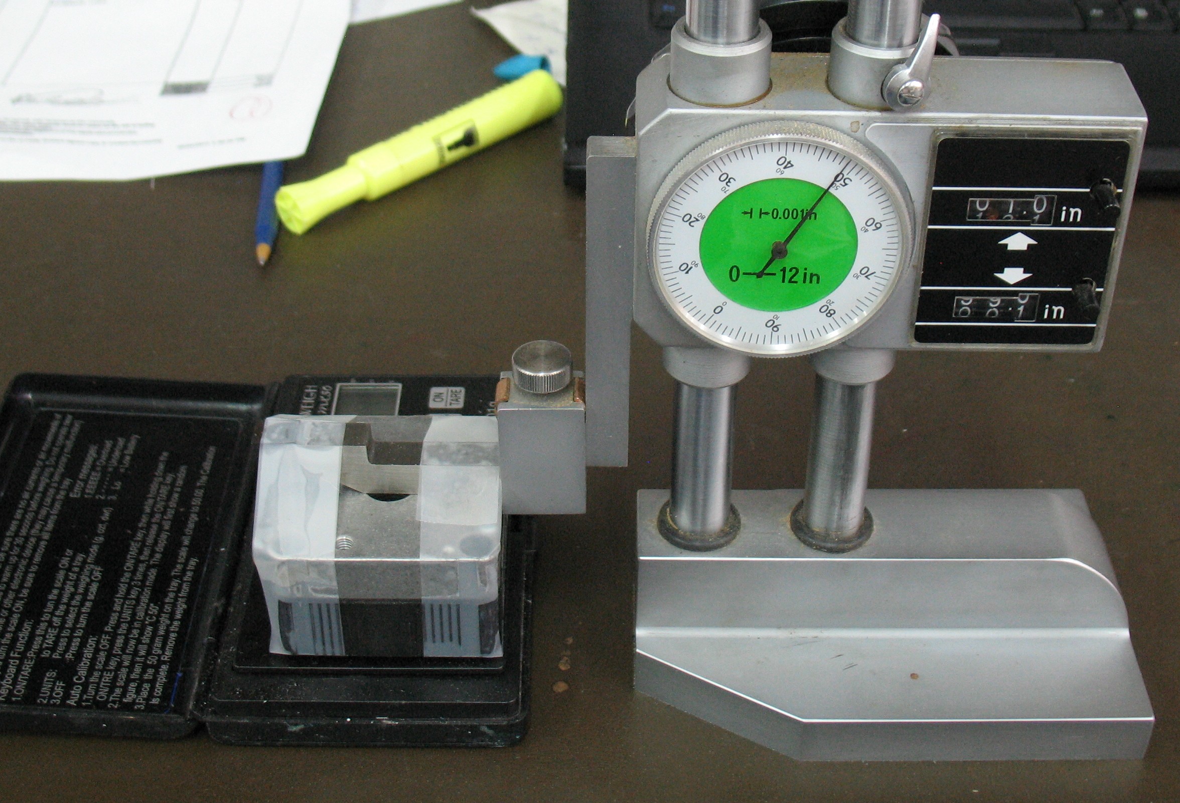
I set up a rather makeshift rig to test the spring strength. The solenoid body with attached rear cover are taped to the arm of a machinist’s height gauge, with the projecting spring push rods just above the pan of a sensitive scale (0-50g×0.01). By lowering the height gauge, the springs are compressed and I can plot the force/distance relationship for all 8 springs working in parallel.
 The result was that the individual springs produce 10.5g/mm, that is, for every mm of compression, they produce 10.5g of additional force.
For the spring to generate enough force to hold the shutter against 20PSI it would have to be compressed by about 1.7mm from its free length. However, based on the cross-sectional drawing from the specifications (assuming that it dimensionally trustworthy) the springs are only compressed about 0.4mm when the shutter is closed. Even with the swollen shutters in my valves, the closed compression is only 0.9mm. In fact the fully-compressed length of the spring is only 4mm less that its free length, so the most force the spring could ever produce is about 42g, enough to hold back about 45PSI.
Clearly, the valves actually designed for NC use have stronger springs in them so they can hold back the rated pressure of 8 bar (120PSI). This is hinted at by the cross-section which shows a spring with heavier wire and only half as many coils as the springs in my valve, although comparing the springs for the compressed and relaxed position in the cross-section show a different coil count, so the spring drawn there may just be a schematic representation.
The Monotype caster only needs about 20PSI to operate it, so rather than using stronger springs, I could make 2mm spacers to insert between the springs and their push rods. This would be enough to seal against about 28PSI, more than enough to run the caster.
Another possibility is to stretch the regular springs by about 2mm, but I would rather avoid making irreversible changes to parts of the valves. This would, however, be much faster than making tiny spacers.
I can also run the valves unmodified in NO mode, where the solenoid supplies the force to resist the air pressure. This just involves a slightly different design for the manifold that supplies the valves, a software change to invert “on” and “off” and more heat generation in the valves because they would spend most of their time energized.
Leave a Reply