
Three years ago I attended SoOnCon 2012 hosted by Diyode in Guelph. The “badge” for this event was an Arduino Uno board, with Codeshield, a shield of general-purpose sensors and actuators, all mounted with a battery pack on a custom-made plastic base that acted as the badge per se:
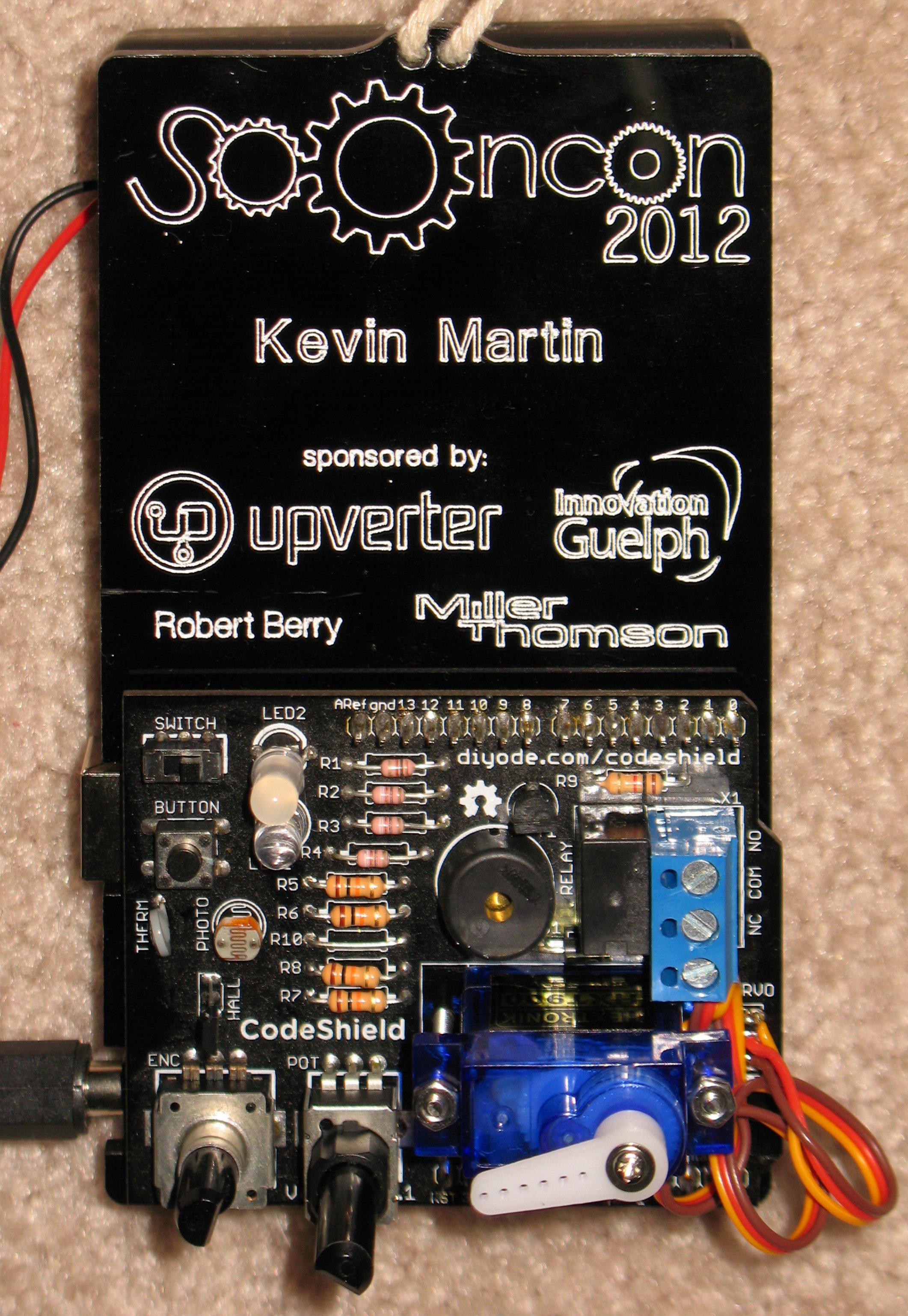 The battery pack is held by Velcro strips, and the Arduino and shield are held because their connecting pins go through matching holes in the badge.
This was provided to the conference registrants as a kit, with the shield board needing full assembly. In the process of assembling mine, I damaged the internal wiring of the servo. I had cut the cable short for a tidy installation, and while stripping the ends of the wires I ripped the connection off the internal board (there is no strain relief on the cable). I opened up the servo and tried to solder the wire back on. Adding to the confusion at the time were some annotations that there was an error in the assembly instructions regarding the connections of the servo.
Once I had the whole thing assembled, everything seemed to work except the servo. I attributed this to the assembly instructions lack of clarity regarding their own error.
I don’t particularly have a use for this, so it has been collecting dust near my desk since then. However, last week I found out that a group from Diyode had visited my daughter’s class to teach them about programming, and they were using this very same shield and Arduino. I figured that I should get the servo working properly so Lily could fool around with it at home.
After re-examining what was still available of the assembly instructions online, looking up the servo specifications, and measuring some voltages on the board, I determined that the servo itself was defective. Obviously, my “repair” did not work. I bought a compatible replacement and wired it in (this time leaving plenty of cable length), and behold! The servo now works!
There is still one oddity, though. The default demo code uses the thermistor to control the LED colour; as you warm up the sensor, the LED should fade from green to red, but instead, the red gradually brightens and the green suddenly goes from full-on to full-off. The Arduino supports PWM control on some of its output pins, and for some reason the runtime library seems to think that my particular model of Arduino does not have PWM support on the pin that drives the green LED. Perhaps the code loaded onto the card was built using the wrong model of processor, one which does not support PWM on this pin, so it reverts to simple on/off.
I still have the IDE on my computer, but I have to hunt down an A/B USB cable so I can reprogram the board.
Leave a Reply