
The next thing to check on my caster was that the cooling system could deliver sufficient water to cool the mould for composition casting. I have a closed-loop system which uses a small fountain pump to force the water up into the cooling system, and cools the drain water in an open coil of copper tubing before emptying it back into the tank.
The fountain pump does not supply much pressure, so the passages in the system must be reasonably clear.
With no mould installed, I turned on the pump and opened all the valves. No water flowed out of the drain pipe. I disconnected the drain fitting on the right side of the caster table near the mould, and no water was coming out there either. Actually, after a few minutes, and small trickle started to appear but nowhere near enough to provide adequate cooling.
I disconnected the inlet to the table cooling port to check if the passages in the table were clogged, but the flow there was just as bad. Finally I disconnected the inlet to the two inflow valves, and got a gusher there. Obviously the valves were barely opening despite having their knobs screwed all the way out.
After shutting off the pump I removed these two valves and their associated piping, disassembled everything and cleaned it. I also removed the cover from the outflow valve whose purpose is to generate controlled back pressure to force cooling water to flow through the mould itself rather than just the caster table.
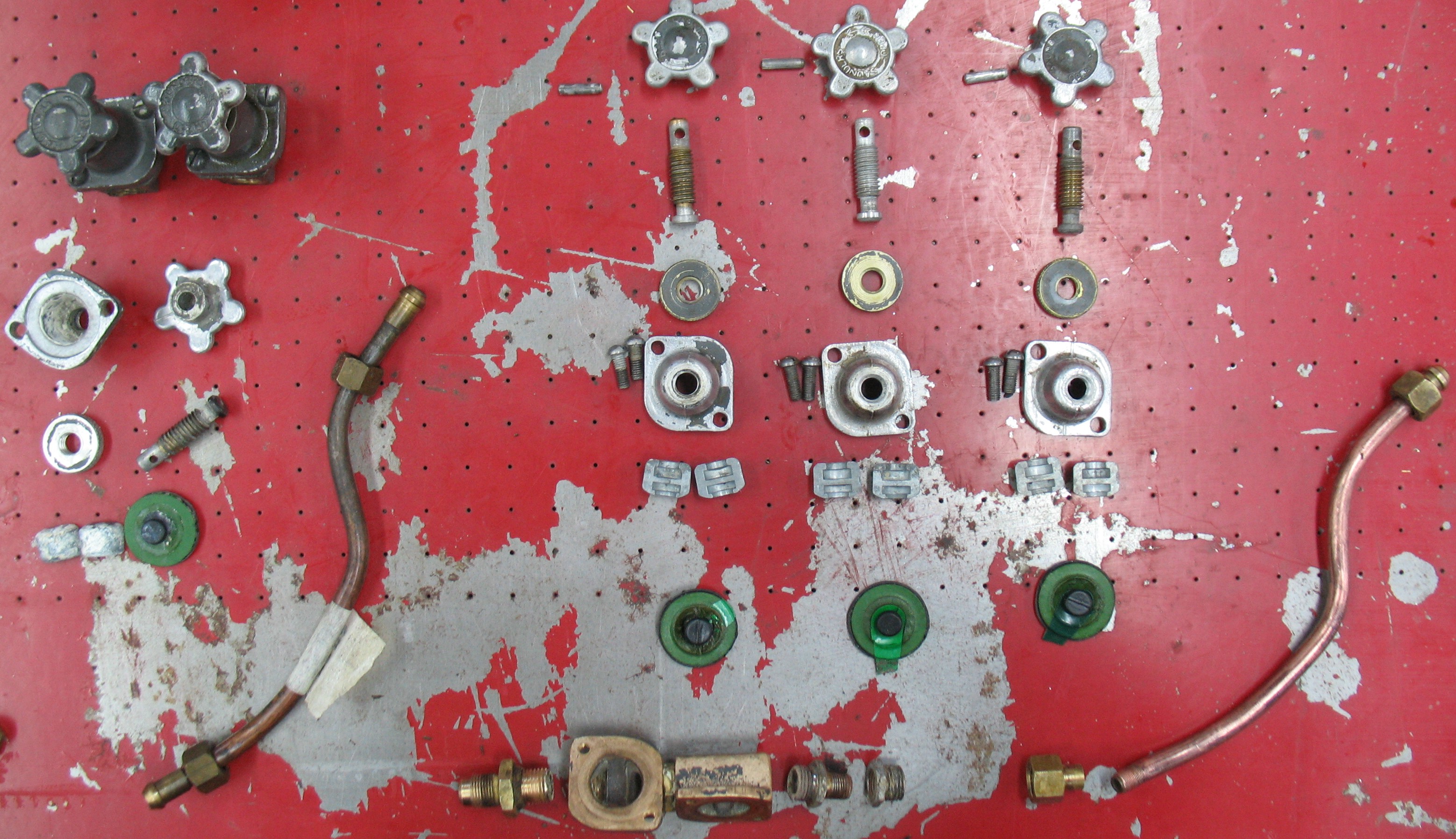
The three valves and associated piping, in pieces, on the right, and some spares on the left.
The valves are of a type called a weir diaphragm valve. The two valve bodies are at the bottom center of the picture. To their right is the water line which runs from the valves to the table inlet fitting. Above these are the three sets of (top to bottom) knobs with taper pin, stem, lock nut, top cover with screws, piston, and diaphragm. Each piston is split with an internal hole to grab onto the end of the stem and onto a button on the back of the diaphragm. Once the valve is assembled, this piston is contained in the cap, preventing the two halves from separating.

The upper half of this diagram, on the Spirax Sarco web site, shows how these valves work. When closed the diaphragm is pressed against the weir to cut off flow. When open, the valve stem pulls the diaphragm up to provide high flow.
One advantage of this style of valve is that none of the moving parts are exposed to the controlled fluid (cooling water, in this case). They also provide fairly good modulation of the flow rate. Unfortunately on my caster, the diaphragms, which might be 50 to 90 years old, are very hard and set in their closed shape since the casters were generally mothballed with these valves closed. Furthermore, on two of them the button that the stem pulls on to open the valve is breaking off so the valve cannot supply much flow unless the water supply pressure is sufficient to push the diaphragm open.
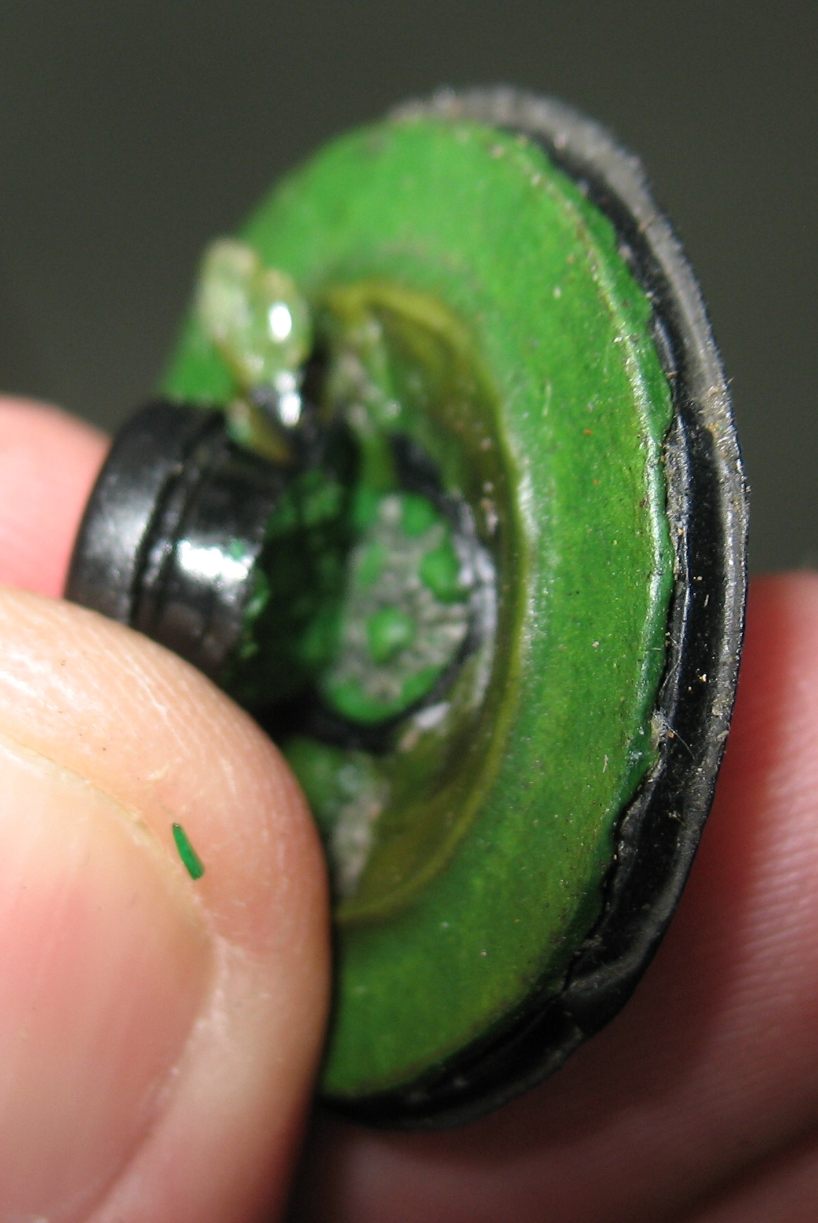
Torn button on back of diaphragm
In my spares I have two complete valves and one valve cap assembly. On examining the two spare valves, it is clear that the diaphragm button is broken on one of them as well. I feel it is unlikely that I could find any replacements to buy, and although I could make most of a diaphragm from sheet rubber, it is not clear how to make and securely attach the button.
Given the shortage of good diaphragms, I decided to save them for the outflow valve, and replace the inflow valves with something more modern.
The caster is fitted with two identical valves in series, and I have never seen a written explanation of this; I guess this is something one would have learned at Monotype School back in the day. My assumption is that one is supposed to set one of the valves to control the desired water flow, and turn the other valve either shut or wide open. In this way the water can be turned on and off without losing the flow setting. I have been trying to use them this way myself but I could never remember which valve I was using for which purpose so I was always losing the flow setting anyway.
For the replacement valves I will use a ball valve for the on/off control, and a needle valve for the flow control. Time to wander through the plumbing department at the local hardware store…
Leave a Reply