
In order to get a good finish when milling the top surface of a part, as I will be doing to prepare matrix blanks, it is necessary that the axis of the mill spindle be perpendicular to the surface of the milling table. If this is not the case, one side of the endmill will cut a bit deeper than the other side, and depending on the relationship between the tilt and the motion, the result will either be a sloped surface or a dished cut, slightly deeper in the center. If multiple passes are made, you get a shallow sawtooth pattern that shows as a ridge at each pass, or sort of a scalloped surface.
The process of adjusting this relationship between the spindle axis and the table is called “tramming” the mill.
On my Sherline mill, I have a spacer block installed between the head and the saddle to allow the mill to cut a bit further from the back edge of the workpiece. The attachment from the head to the spacer and from the spacer to the saddle are the same: A central post has a beveled groove cut into it, and a bevel-tipped locking screw presses sideways against this, acting as a wedge and pulling the post tight. Tramming the mill consists of making a minute rotational adjustment of the head about the post so the spindle axis is perpendicular (side-to-side) to the table. The joints also have keys to hold the head roughly vertical or horizontal, but the keyways have enough play in them that they can’t assure enough accuracy.
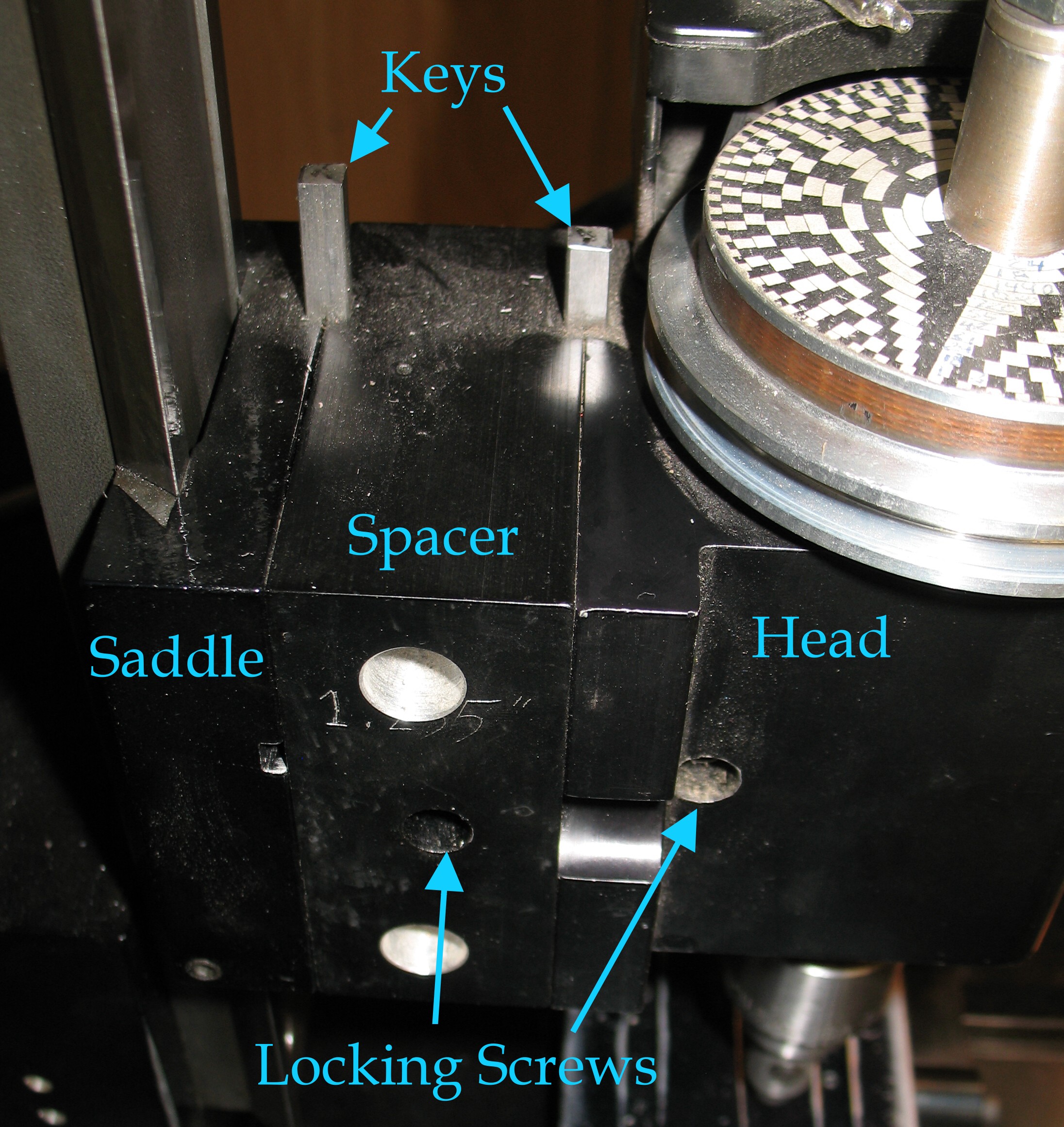 This joint, in my opinion, could benefit from more holding power. As it is currently designed, vibration and/or unexpected (or expected!) high cutting forces can knock the mill out of tram. Having the weight of the motor all on the right side of the pivot post tends to mean that the head eventually ends up out of tram, high on the left, by as much as the keys in the joints allow.
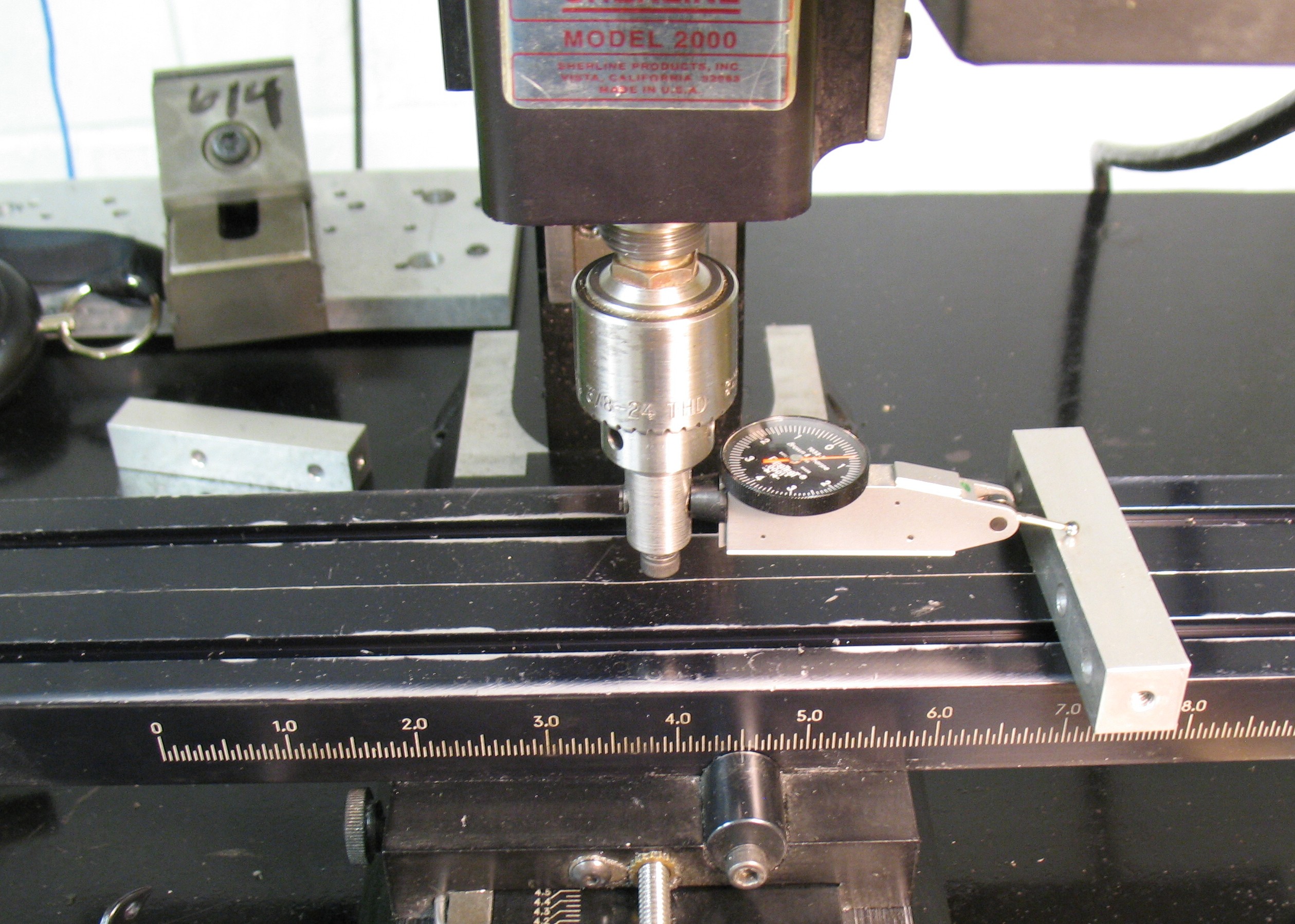
To test the tram of the mill, a test indicator is mounted sideways on the spindle. On my mill I use the drill chuck and a right-angle adapter to do this. The feeler of the indicator is about 3″ from the spindle, and the indicator reading shows how much the feeler is being pushed up by the block placed under it.
 I adjust the Z position until I have a non-zero reading on one side, then manually rotate the spindle to the other side, and using the same block, take another reading. Ideally the readings should be the same. The adjustment is made by very slightly loosening the locking screw on the head mount, twisting the head in the appropriate direction, re-tightening the locking screw, and measuring again. It is somewhat of a hit-or-miss procedure: sometime you don’t adjust far enough, and sometimes you go too far, even ending up more out of tram but in the opposite direction.
This evening I got it to this condition:
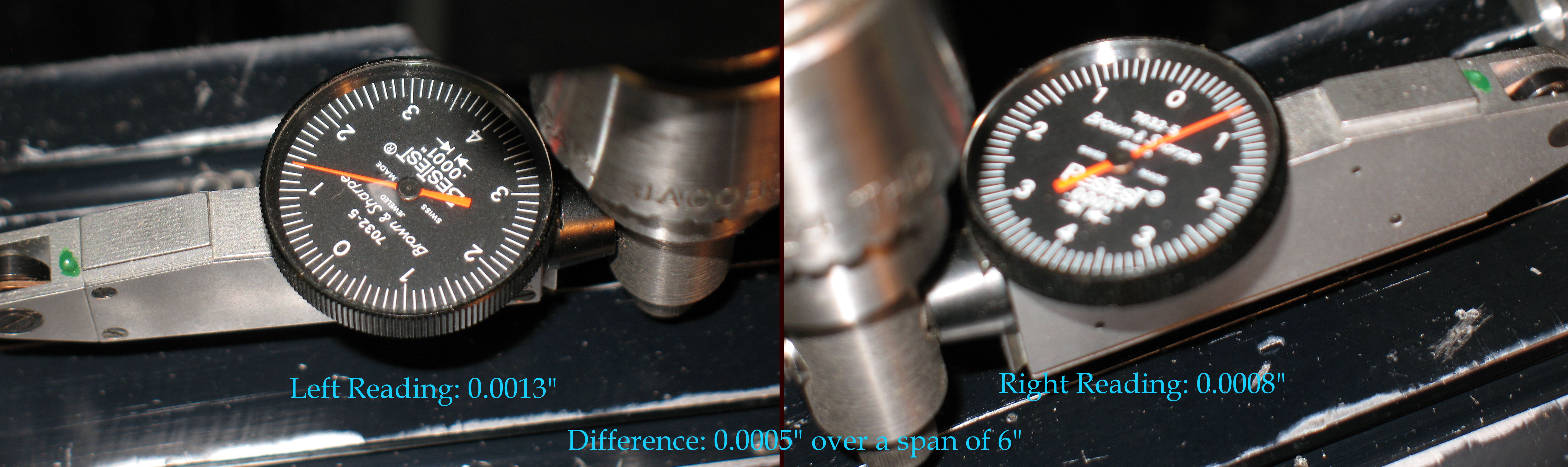 The readings differ over a 6″ span by 0.0005″ (half a thousandth of an inch), or about 1 part in 10,000, which is about as good as I can hope for with the hit-or-miss adjustment. To put this value in perspective, if I were to use a ⅜″ endmill to finish the top of a part in multiple passes, the ridges from the “sawtooth” surface would be 0.375/10,000 i.e. 0.0000375″ high, certainly not noticeable by feel, and perhaps not even visually.
When the mill is as out of tram as the keyway play allows, there is about 0.010″ difference, or about 1 part in 600, and multiple passes with the ⅜″ endmill would produce ridges 0.000625″ high, easily found by feel. I had already noticed this when I was making a point block for an American Monotype display mould, although further hand-finishing steps made the ridges unimportant for that project.
For finishing matrices, I would use a fly cutter, which cuts like a 1.5″ endmill would. It would be done in a single pass, so the main concern would be the dishing which would leave the centre of the matrix low. As it turns out the depth of this dishing would be about the same as the ridge height just calculated. A matrix 0.000625″ low in the centre would be unacceptable; one that is 0.0000375″ low would be excellent.
With the mill set up as it is, and provided that I don’t try any heavy cuts that might knock it out of tram again, I should be able to mill the ⅛×¾” brass bar stock I have to the proper thickness for making the matrices and be assured of flat and parallel surfaces.
Leave a Reply