
I’ve started tracing all the pneumatic plumbing on my Monotype caster, and at least now I’ve identified all the various control valves hanging off the table apron. This may be old news to any Monotype pros who may be out there, but I have found that the documentation for these various valves is scattered throughout at least three different books, and even at that it is often incomplete. I have found nothing discussing the compatibility of trying to use several of these options at once, or their compatibility with the three different matcase sizes.
The left side apron below the paper tower
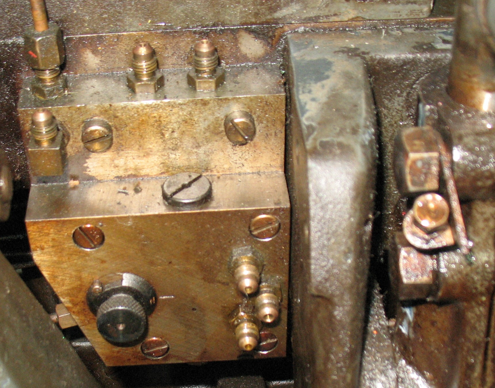
On the left side of the table below the paper tower is a valve and mounting plate which serves two purposes:
The mounting plate serves as a distribution manifold for the Quadding & Centering system via the four flare fittings pointing upwards and three connections on the rear.
Attached to the mounting plate is the control for the Unit Shift system. The knob on the left turns the Unit Shift system on and off, and the three flare fitting on the right connect to a hold valve which on each cycle stores the Unit Shift selection from the end of reading the ribbon up until the matrix jaws close fully (during this time the ribbon is being advanced to the next position). This hold valve is not installed in this photo, but it is reset at the closing of the jaws by the small bolt head visible on the right, attached to the cam lever arm for all the jaw motion.
A caster without Unit Shift might have a dummy plate here instead of the control plate, or the mounting plate might be a smaller version that does not have any provision for Unit Shift at all.
Rear apron of table
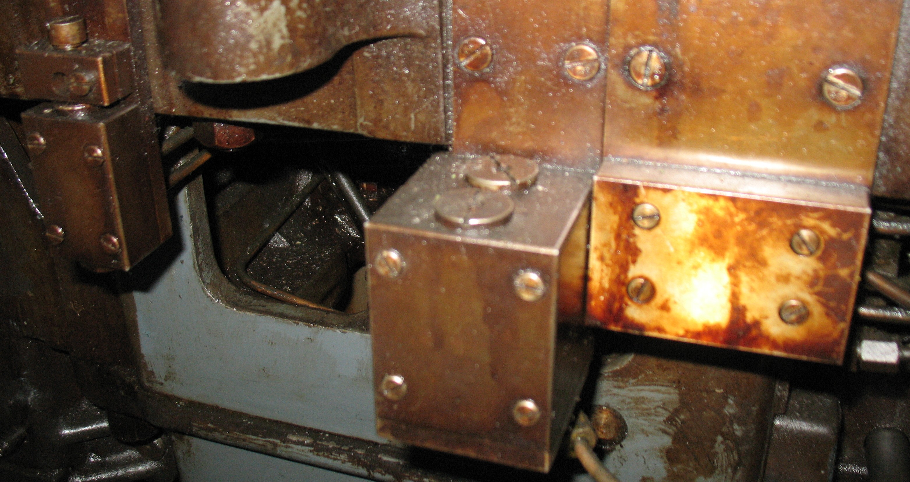
On the rear apron of the table there are three pneumatic controls. As shown in the photo, left to right, they are the pneumatic mould blade signalling, Quadding & Centering control, and Unit Adding control. Each of these is attached to a mounting plate that hangs from the edge of the table and has several under-table air lines feeding into the rear of the plate.
I use the general term “pneumatic mould blade signalling” because the same valve is used in several different ways depending on the actual mould in use. This uses a ribbon signal instead of special mats with shallow cone holes to select one of two alternative ways for the mould to open. One possibility is the signalling for low quads on a standard composition mould, allowing one to make low quads on any row of the matcase and thus of pretty much any width. Another possibility is controlling the Duplex Mould whose upper blade only covers the top half of the cavity, used to suppress the casting of a diacritical mark (e.g. an accent) above the main character in the mat. There is also a triplex mould which requires two air signals; in this case this valve would have a twin beside it to control the second signal. In any case use of this signal requires support on the bridge and (in the case of the American bridge) another valve on the table top near the right rear corner. Turning this option off or on is done by inserting or withdrawing the large screw that projects from the top of the control valve.
Quadding and Centering are controlled by the two stacked valves at the center of the photo. These valves resolve the signals from the paper tower to determine if either of these features should be engaged, and the resulting air signals are routed through the base plate mentioned above, on the left apron below the paper tower. From there they go to two actuators on the paper tower and one valve at the end of the galley. There is no way of turning this option on or off.
Unit Adding is controlled at the valve located at the right in the photo. My caster is not equipped with this option, and so the valve is replaced by a blank plate that routes the air lines as if the option were turned off. With the option installed, there is a knob on top of the valve which turns the option on or off. The field-repaired air lines shown in a previous post are supposed to feed into the back of this valve’s mounting plate.
Not shown is the valve for use with 17-column (instead of 15-column) matcases. This valve is located near the left rear corner of the rear airpin block, and has a knob to enable or disable this option.
Of all of these options, only Quadding and Centering is made obsolete by driving the caster by computer. All of the others give the computer more versatility in terms of adjusting type width or generating low quads. Yet this option is the only one that cannot be turned off.
Over the next few days I will be removing and cleaning all these valves to ensure they operate properly.
Hi,
thanks for your entry, it’s been quite helpful. I’m getting our composition caster to run (computer-controlled, too 🙂 – I’m working on my version of an interface built around a Raspberry Pi), and I’ve noticed that NI and NL pins are not working, so I decided to look into the matter. First, I looked under the table, searched for two tubes closest to the mould and thought that these lines are NI and NL, activated by the 216E valve box (which is for Q&C). I did strip, clean and rebuild it. Later on, it turned out that 14 tubes go to the rear pin block instead of 16, and the tubes I thought to be NI and NL were in fact A and B. So, the valve for NI and NL must have been somewhere on the pin block. Then I’ve noticed 30C… stripped and cleaned it too.
Yes, the valve for NI and NL is integrated into the pin block and there is no separate tubing for this. This valve is exposed at the top and close to the pot so is subject to gumming up with oil and other crud. The valve and its manifolds is attached to the side of the pin block by 3 (?) screws so, except for limited access to one of the screw heads, it can be removed and dunked in solvent to clean it. This valve also integrates a control knob to enable or disable the 17-column option. Having it enabled with a 15×15 matcase and a mispunched ribbon could crash the centering pin into the side of the matcase.
One problem Bill Welliver encountered with his computer interface is that some air lines need extra air volume to work properly. For instance, the N line has to drive both the N air pin but also the valve for the 17-column matcase (NI and NL).
Perhaps it is a typo or has multiple part symbols, but the NI/NL valve unit is part symbol 40C. If it is operating properly you should see the valve stem pop up every time N is signalled.