
With the crossblock and blade reassembled, the rest of the mould goes together quickly. All of the remaining parts are built onto the base plate.
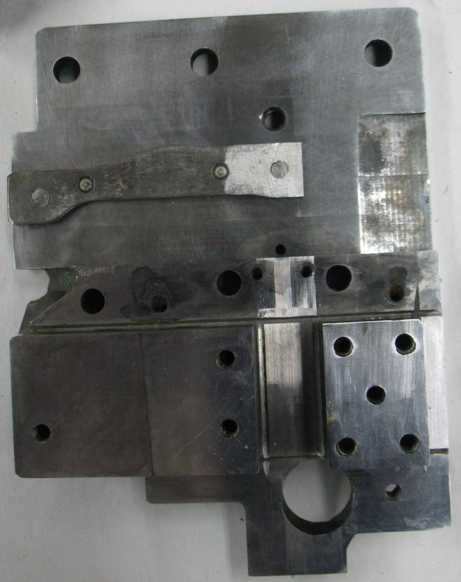 The first parts to go on are the cam which operates the jet ejector as the crossblock moves sideways, and the squaring plate on which the parts forming the mould cavity are built. The cam is positioned by two dowels which I did not remove from the base, and secured by two screws inserted from the underside of the base plate. The squaring plate is held by five screws from the underside of the base plate and does not have anything to provide positive positioning. I set it in about the middle of the play provided by its screw holes, but as I later found out its position is more critical than I had thought.
 The next parts to install are the left and right type blocks. The larger right block (on the left in the photo) also has two plug screws for oil passages and two felt pads to meter out the oil, which I installed into the block beforehand.
Each of these blocks has screws securing it against the squaring plate in three dimensions: one at the outer end pushing the two blocks towards each other, one or two through the boss of the squaring block to pull the type block back, and one or two from below through the base plate to hold the type block down.
As with the screws in the crossblock, these must be tightened gradually in sequence to ensure the type block is seated properly.
If all goes well, at this point, the mould blade can be inserted by sliding it in from the back. In my case, one of the felt pads (the one that oils the side of the blade) was not fully into its hole, so the blade actually had to shear off some of the fibres from the felt. As a result the initial insertion was tight, but it quickly loosened up as the sheared-off fibres worked out of the sliding area.
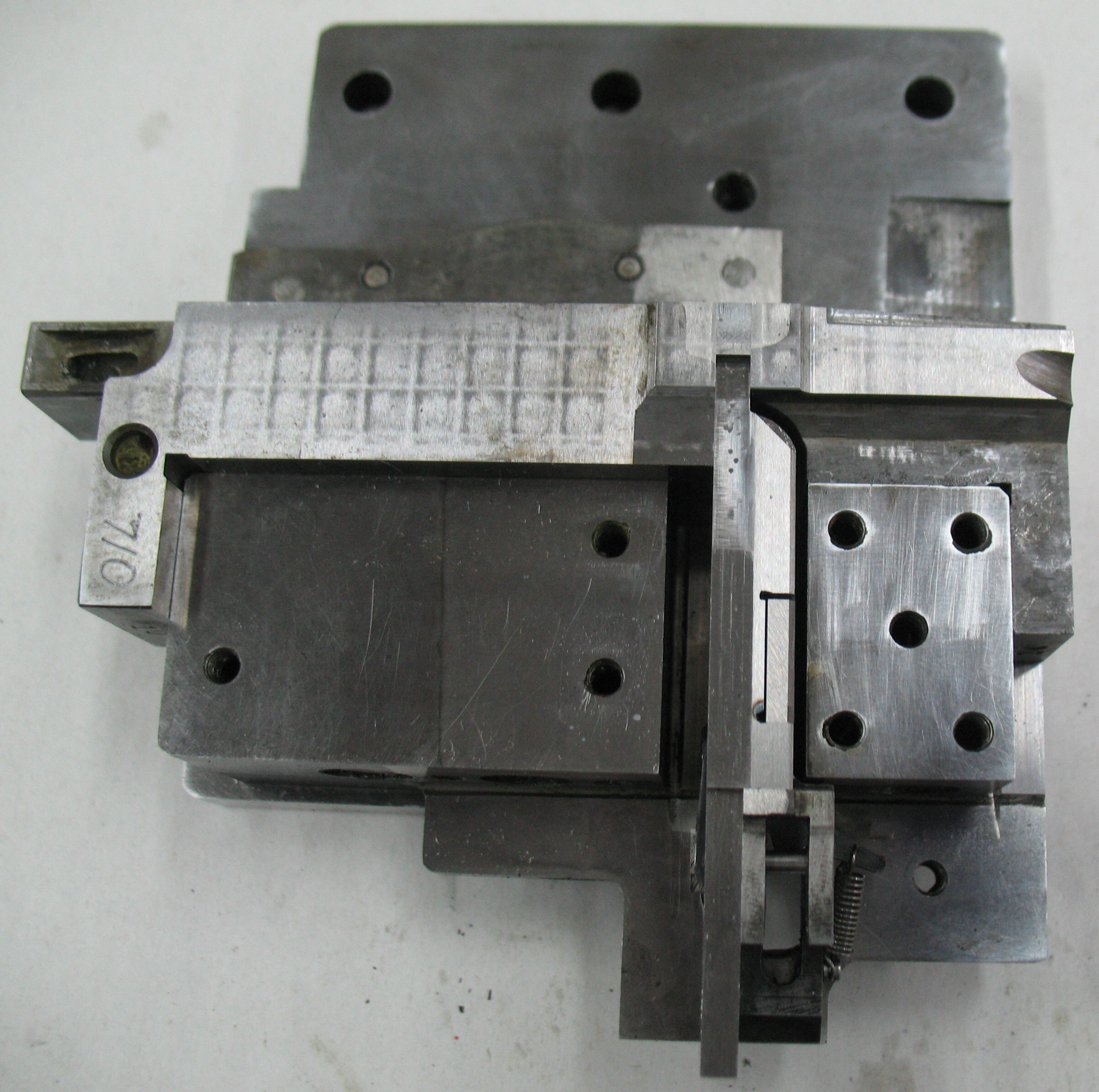
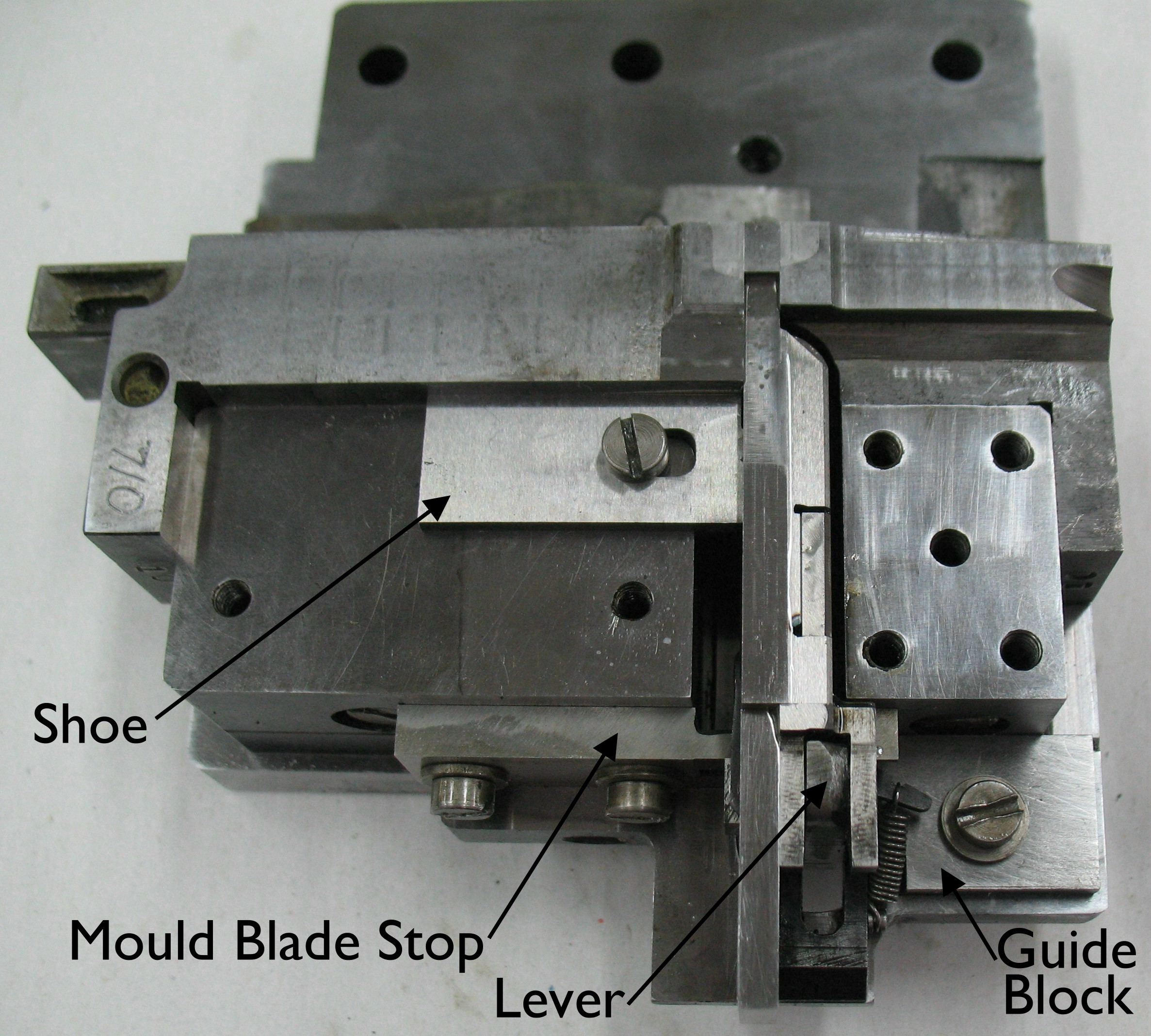 Three small parts that retain and guide the blade are installed next. The are the right mould blade shoe which holds the main blade down and limits how far it can open, the mould blade stop which limits how far the mould blade can close, and the mould blade carrier guide block which prevents the back end of the blade from moving sideways. The back surface of the mould blade stop has been precision ground at the factory so the mould blade, when closed, is exactly flush with the front faces of the two type blocks. At this point I also dropped the upper blade operating lever into place on its pin on the blade carrier.
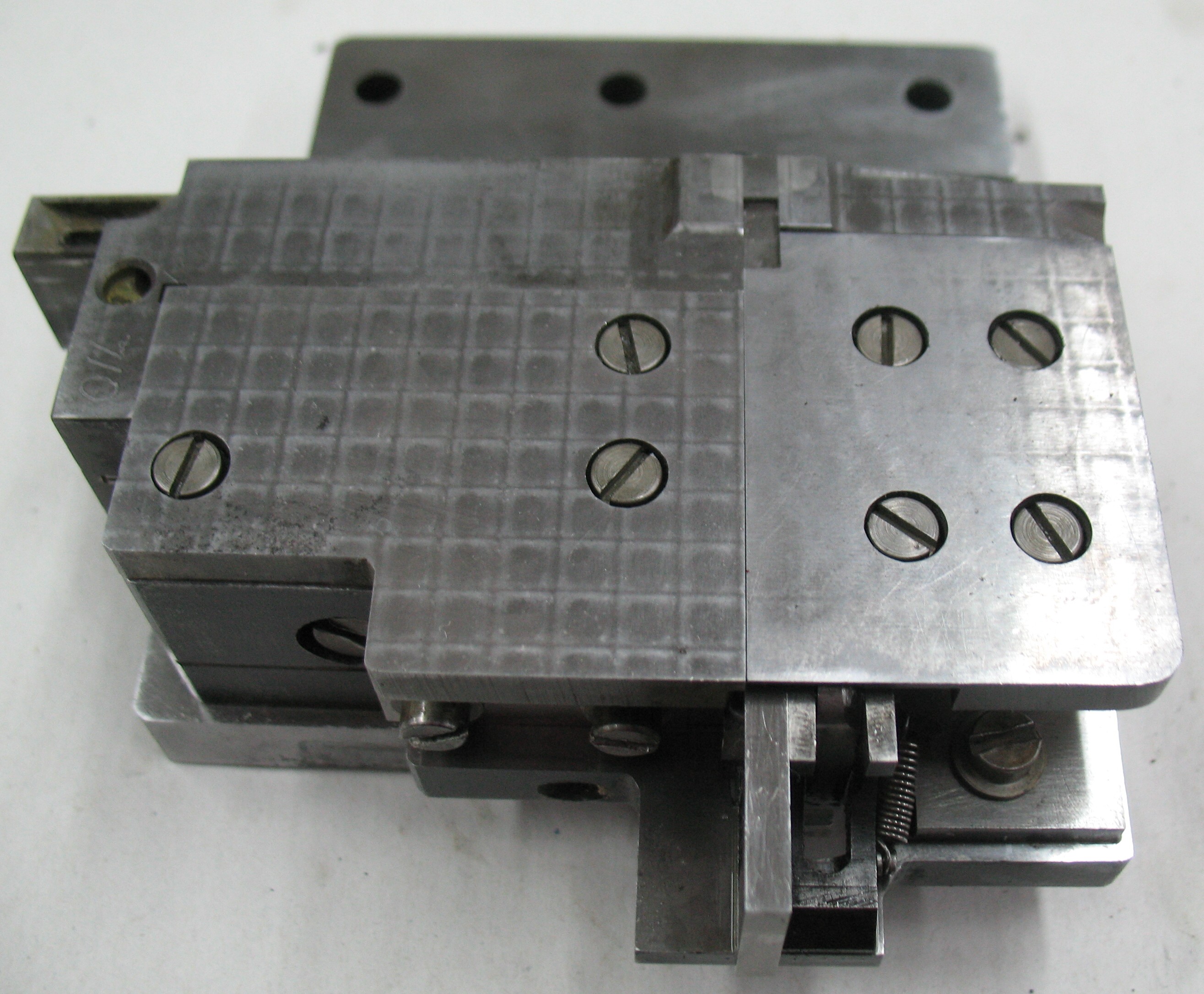 The two covers are installed next. The left cover (the one with four screws) is also called the left mould blade shoe because it completes the guide that the blade slides in. It both holds the upper blade down and also prevents it from shifting to the left. The right cover (the one with two screws; the apparent third screw is actually the one holding the right mould blade shoe in place) is also called the mould blade top guide as it prevents the blade from shifting to the right.
The last part to assemble and install is the apron, or front abutment. It includes the nameplate and the crossblock shoe along with its adjusting screws and locknuts. It is held to the base plate by three large screws from below.
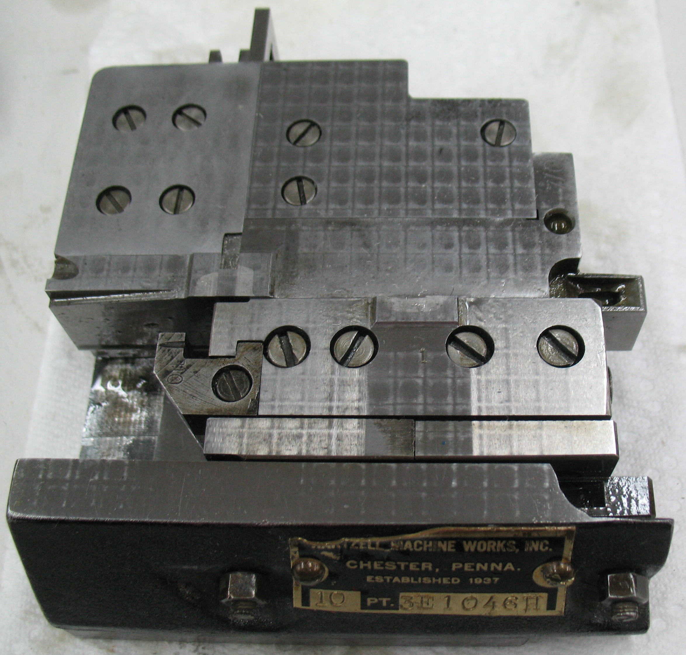 I slid the crossblock into place, and as with the mold blade, the felt pad (the one on the crossblock) was not tucked back into its hole neatly. However, in this case I could reach the pad to tuck it into its cavity as the block slid in. I slid the block to the position in the photo and tightened both shoe adjusting screws tight and left them that way for a while to seat the felt.
Later (after taking the photo) I backed off the adjusting screws a tiny bit (less that a tenth of a turn) and tightened their locknuts.
Everything moved freely and was now well oiled so I put the mould in place on the caster (using only the two clamps, not the blots from below). On turning the caster handwheel by hand I found to my dismay that the caster would not operate smoothly. The type carrier appears to be rubbing on the front face of the left type block.
Some thought on which parts mount where leads to the conclusion that this interference is caused by incorrect placement of the squaring block. Evidently on factory assembly these are installed using some sort of fixture to hold the squaring block at the right location on the base plate.
To correct this I don’t have to disassemble everything; I should just be able to loosen the eight screws that hold the squaring block and type blocks to the base plate. Before doing this, though, I will have to measure some other moulds to determine how far the type block fronts should be from the rear edge of the base plate. If they are too far the type carrier will rub the type block as I observed. If they are too close the type carrier will fail to pick up very narrow pieces of type as they eject from the mould cavity.
The next post should include the results of these measurements and the correction of this mould’s squaring block position.
Leave a Reply