
After deciding to replace some of the valves that control the cooling water flow on my caster, I made a visit to a few hardware stores. I came home with a ball valve and a needle valve but as they did not have the correct pipe connections I also bought two adapters.
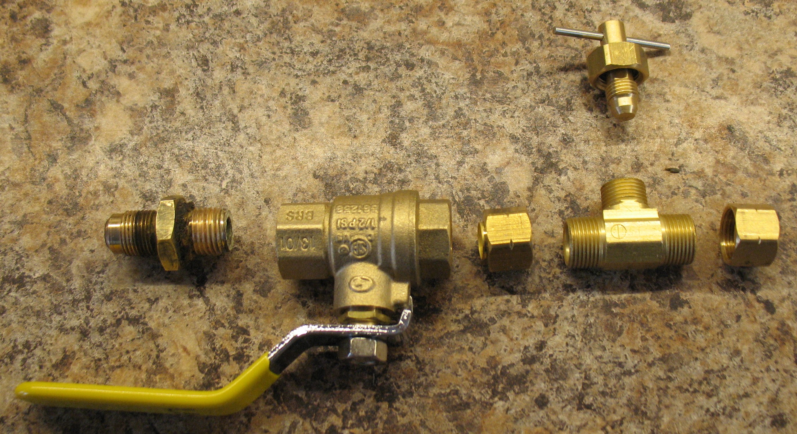
The valves I purchased. Main row (L-R) are the original supply flare fitting, the ball valve, a ⅜″ compression nut, the body of the needle value, and another ⅜″ compression nut. Above is the valve needle and cap.
The ball valve has ¼″ FPT (Female Pipe Thread) connections, which are fine. The flare fitting that connects to the supply line will attach directly to this valve.
The needle valve was unfortunately only available with ⅜″ compression fittings. In order to fit this to the ball valve and to the line that carries the water to the table and mould, I also bought two adapters from ¼″ MPT (Male Pipe Thread) to ⅜″ compression. I would also have to dig through my supplies for a couple of short lengths of ⅜″ soft copper tubing.
It turned out there were three downsides to this approach. One is that the combination of all these adapters and connections would make the valve unit too long to fit in the original valves’ location. Another is that all these connections are potential points of leakage. Finally, closer measurement revealed that the fitting to on the line to the table does not attach onto ¼″ MPT as the thread pitch is wrong.
The compression ends on the needle valve could not be directly modified to another thread type because there was not enough metal thickness to cut different threads. What I did instead was to modify one of the compression adapters I had bought to slip into one of the compression sockets and to make another adapter from scratch for the exit fitting that also slipped into the compression fitting, and solder both these directly to the needle valve.
Cutting these to fit into the compression fitting was fairly easy, and the solder would fill in plenty of sloppy measurement. The outlet fitting turned out to need 19 threads per inch on an odd diameter. To do this on my lathe I had to replace a 24-tooth gear in the carriage drive with a 60-tooth one, and select 48 threads per inch on the gear box (which had no 19TPI setting). This would make the lathe cut at 19.2 threads per inch (48×24/60) which is close enough. I did test fittings of the matching nut to determine when the threads had the correct diameter.
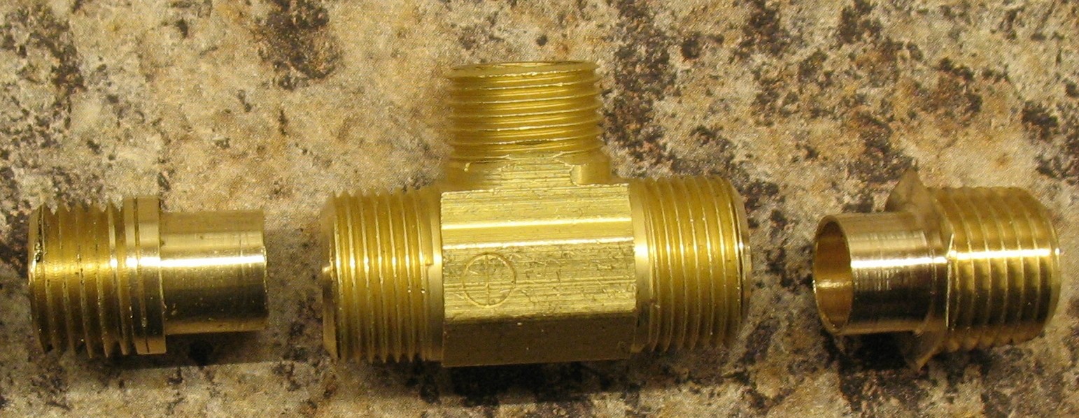
The needle valve and custom adapters, ready to solder in. The one on the left is the oddball 19TPI straight thread, and on the right is the 1/4″ MPT.
After soldering the adapters onto the needle value, I loosely assembled the two valves and verified that the assembly is about the same length as the original valve pair.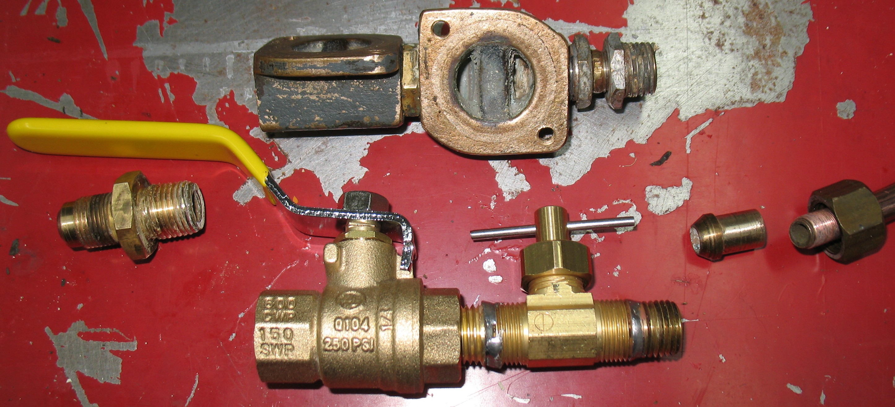
I assembled these using Teflon tape on the pipe thread joints and thread sealing compound where the cone ends screw onto the ends of the copper tube. With everything installed on the caster, the water valves look like this:

The repaired outlet valve is at the upper left and the two new inlet controls on the right. There is no longer any chance of confusing the flow control and the water shutoff. A trial run indicates excellent flow rate and good control using the needle valve.
Leave a Reply