
In order to make an 18 point spacer for use in a US Monotype Display Mould, I first have to determine the dimensions required. I set up a spreadsheet for recording the data and measured the dimensions of all the spacers I had.
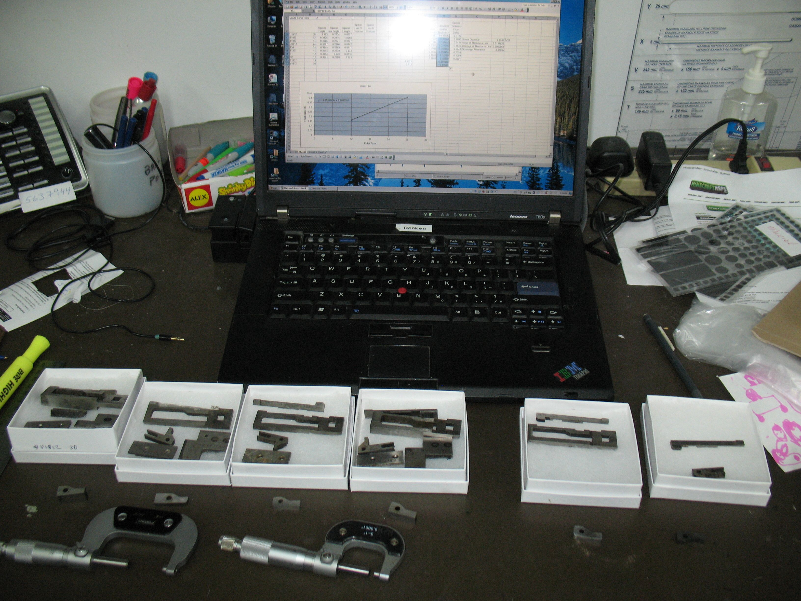
Measuring the spacers with micrometers and entering the measurements into Excel
My first observation is that, except for the thickness, there is a lot of variation in the dimensions, with differences of up to 0.010″ from one spacer to the next. This will mean making a replacement spacer should be relatively easy in terms of machining the outline of the part.
My other observation is that there seem to be two styles of blade and correspondingly two sizes of spacers:
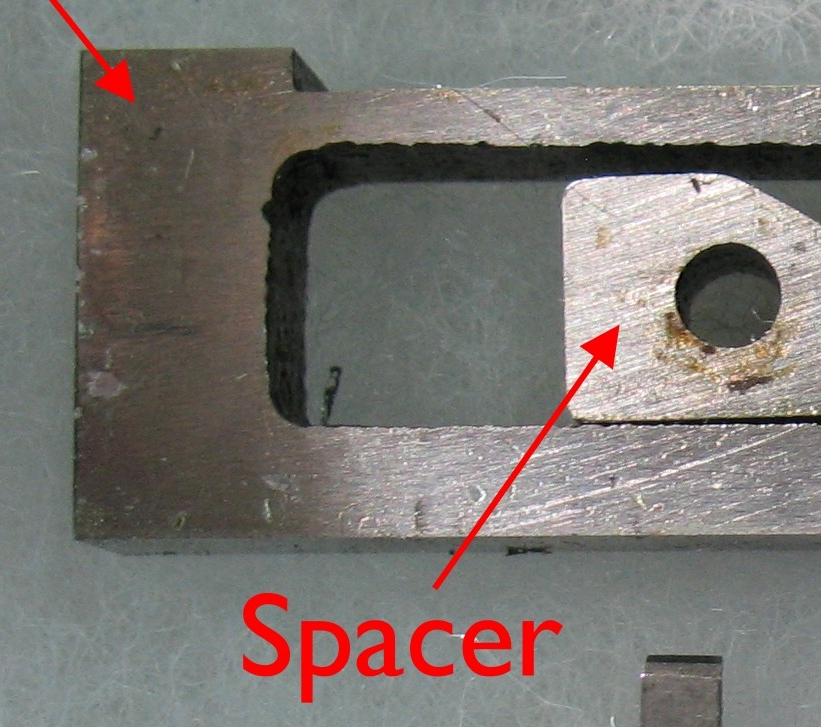
On the left the blade has a thick end, about 5/16″, and the spacer is about 7⅞″ long. On the right, the blade has a thinner end, about 3/16″, and the spacer (not shown) is 11/16″ long with most of the extra length to the left of the hole. In addition to determining the space between the two type blocks, the spacer also acts as a stop limiting how far the blade can open. Installed and properly adjusted in the caster, this stop is never used (the sizing mechanism limits the mould blade opening), but when the mould is out of the caster, this spacer holds the blade from coming out completely. Ideally, the blade should not be able to pull out enough to disengage the nick wire in the left type block from the nick machined in the side of the blade. If the blade comes out further than this, there is the possibility of damage when closing the blade again if the nick wire improperly reengages with the blade nick. The only thing holding the nick aligned is the front blade cover (shoe).
If a short spacer is used with a thick-end blade, or a long spacer with a thin-end blade, this stop seems to work properly, keeping the nick engaged. But as I mentioned in my previous post about blade kits, the spacers are not serial numbered and can become interchanged between kits, leading to the inappropriate use of a short spacer with a thin-front blade. Several of my blade kits are like this. Conversely, a long spacer combined with a thick-end blade will limit the blade opening; this is unlikely to be a problem for small sizes, but 36-point display type requires the mould blade to open to 48 points, and the long spacer might prevent this.
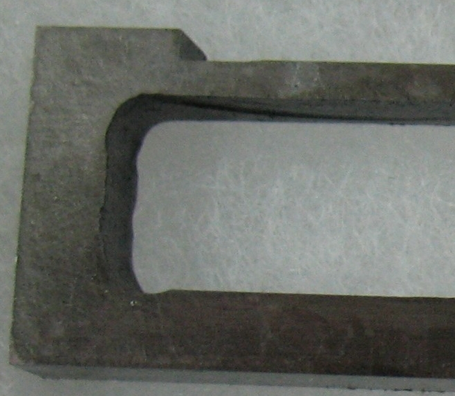
Note also the rough finish to the opening in the blade, again indicating that high precision machining of the spacer is unnecessary.
The thickness of the spacer, on the other hand, is very important, as it determines the body size of the type. The spacer holds the left and right type blocks apart during mould assembly, but once everything is together and both type blocks have been tightened down, the spacer really only acts as a blade stop. I measured the thickness of all the spacers I had and correlated this to their nominal size, and found that they are about 0.36% thicker than their nominal size. This is to allow for the shrinkage of the type as it cools from the type metal’s solidification temperature to room temperature. The thickness measurements were done with a micrometer, which measures to 0.0001″ (a little better than 1/100 of a point), but I found that the thickness of individual spacers varied by up to ±0.0003″ from the exact 0.36% oversize. This variation did not correspond in any way with the serial number of the mould, but as I mentioned, the spacers can be interchanged between kits.
Just in case this represents measurement error, I will re-measure the thicknesses by comparing each spacer thickness against a set of gauge blocks. This will be done using the following setup, with which I was checking the thickness consistency and parallelism of the spacers:
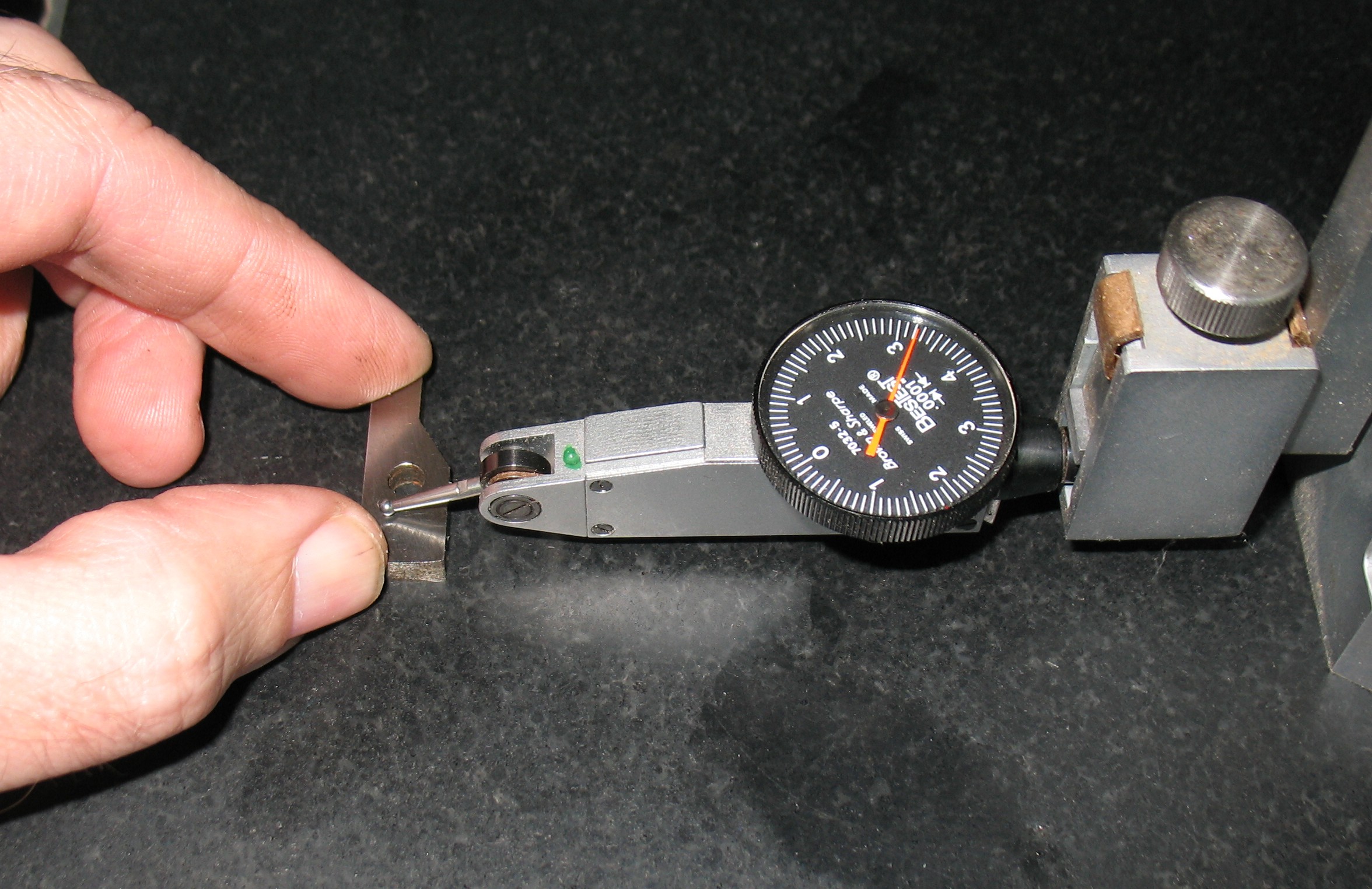
The dial indicator is clamped to the head of a height gauge, and the latter is adjusted to a height that gives a non-zero reading on the indicator and then locked so it does not shift. Everything is set on a granite surface plate. This does not give an actual thickness measurement, but by sliding the spacer around under the tip of the indicator, I can see how much the thickness varies. The small graduations on the indicator are 0.0001″ and in this case the thickness varied by a bit less that that. By replacing the spacer with gauge blocks, I can obtain an exact (as exact as the tolerance of the blocks) thickness.
I also still have to measure the hole size and position. One other observation to simplify my machining work is that this spacer does not rub on anything nor is it subjected to any impact or localized pressure. As a result it does not have to be hardened so I can make my new spacer from low-carbon steel, which will be easier to machine than a hardenable grade of tool steel.
Leave a Reply